Information injection-pump assembly
BOSCH
9 400 614 989
9400614989
ZEXEL
101602-9900
1016029900
NISSAN-DIESEL
16712Z5507
16712z5507

Rating:
Service parts 101602-9900 INJECTION-PUMP ASSEMBLY:
1.
_
5.
AUTOM. ADVANCE MECHANIS
6.
COUPLING PLATE
8.
_
9.
_
11.
Nozzle and Holder
12.
Open Pre:MPa(Kqf/cm2)
22.6(230)
15.
NOZZLE SET
Cross reference number
BOSCH
9 400 614 989
9400614989
ZEXEL
101602-9900
1016029900
NISSAN-DIESEL
16712Z5507
16712z5507
Zexel num
Bosch num
Firm num
Name
101602-9900
9 400 614 989
16712Z5507 NISSAN-DIESEL
INJECTION-PUMP ASSEMBLY
FD6 * K
FD6 * K
Calibration Data:
Adjustment conditions
Test oil
1404 Test oil ISO4113 or {SAEJ967d}
1404 Test oil ISO4113 or {SAEJ967d}
Test oil temperature
degC
40
40
45
Nozzle and nozzle holder
105780-8140
Bosch type code
EF8511/9A
Nozzle
105780-0000
Bosch type code
DN12SD12T
Nozzle holder
105780-2080
Bosch type code
EF8511/9
Opening pressure
MPa
17.2
Opening pressure
kgf/cm2
175
Injection pipe
Outer diameter - inner diameter - length (mm) mm 6-2-600
Outer diameter - inner diameter - length (mm) mm 6-2-600
Overflow valve opening pressure
kPa
157
123
191
Overflow valve opening pressure
kgf/cm2
1.6
1.25
1.95
Tester oil delivery pressure
kPa
157
157
157
Tester oil delivery pressure
kgf/cm2
1.6
1.6
1.6
Direction of rotation (viewed from drive side)
Right R
Right R
Injection timing adjustment
Direction of rotation (viewed from drive side)
Right R
Right R
Injection order
1-4-2-6-
3-5
Pre-stroke
mm
3
2.95
3.05
Beginning of injection position
Drive side NO.1
Drive side NO.1
Difference between angles 1
Cal 1-4 deg. 60 59.5 60.5
Cal 1-4 deg. 60 59.5 60.5
Difference between angles 2
Cyl.1-2 deg. 120 119.5 120.5
Cyl.1-2 deg. 120 119.5 120.5
Difference between angles 3
Cal 1-6 deg. 180 179.5 180.5
Cal 1-6 deg. 180 179.5 180.5
Difference between angles 4
Cal 1-3 deg. 240 239.5 240.5
Cal 1-3 deg. 240 239.5 240.5
Difference between angles 5
Cal 1-5 deg. 300 299.5 300.5
Cal 1-5 deg. 300 299.5 300.5
Injection quantity adjustment
Adjusting point
A
Rack position
9
Pump speed
r/min
750
750
750
Average injection quantity
mm3/st.
45.2
43.6
46.8
Max. variation between cylinders
%
0
-2
2
Basic
*
Fixing the lever
*
Injection quantity adjustment_02
Adjusting point
C
Rack position
7.5+-0.5
Pump speed
r/min
300
300
300
Average injection quantity
mm3/st.
10
8.2
11.8
Max. variation between cylinders
%
0
-12
12
Fixing the rack
*
Test data Ex:
Governor adjustment
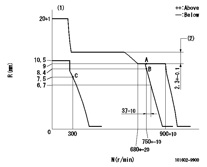
N:Pump speed
R:Rack position (mm)
(1)Target notch: K
(2)Rack difference between N = N1 and N = N2
----------
K=15 N1=750r/min N2=450r/min
----------
----------
K=15 N1=750r/min N2=450r/min
----------
Speed control lever angle
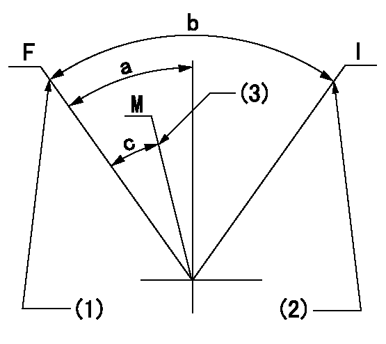
F:Full speed
I:Idle
M:Minimum-maximum speed
(1)Set the pump speed at aa. (At delivery)
(2)Stopper bolt setting
(3)Set the pump speed at bb.
----------
aa=900r/min bb=750r/min
----------
a=8deg+-5deg b=21deg+-5deg c=5deg+-5deg
----------
aa=900r/min bb=750r/min
----------
a=8deg+-5deg b=21deg+-5deg c=5deg+-5deg
Stop lever angle

N:Pump normal
S:Stop the pump.
----------
----------
a=26.5deg+-5deg b=53deg+-5deg
----------
----------
a=26.5deg+-5deg b=53deg+-5deg
0000001501 GOV FULL LOAD ADJUSTMENT
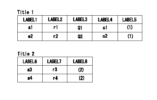
Title1:Full load stopper adjustment
Title2:Governor set speed
LABEL1:Distinguishing
LABEL2:Pump speed (r/min)
LABEL3:Ave. injection quantity (mm3/st)
LABEL4:Max. var. bet. cyl.
LABEL5:Remarks
LABEL6:Distinguishing
LABEL7:Governor set speed (r/min)
LABEL8:Remarks
(1)Adjustment conditions are the same as those for measuring injection quantity.
(2)-
----------
----------
a1=A a2=B r1=750r/min r2=750r/min Q1=48.6+-1.6mm3/st Q2=45.2+-1.6mm3/st c1=+-2% c2=+-2% a3=18 a4=15 r3=900r/min r4=750r/min
----------
----------
a1=A a2=B r1=750r/min r2=750r/min Q1=48.6+-1.6mm3/st Q2=45.2+-1.6mm3/st c1=+-2% c2=+-2% a3=18 a4=15 r3=900r/min r4=750r/min
Timing setting

(1)Pump vertical direction
(2)Position of gear's standard threaded hole (position of gear mark 'H') at No 1 cylinder's beginning of injection
(3)B.T.D.C.: aa
(4)-
----------
aa=19deg
----------
a=(60deg)
----------
aa=19deg
----------
a=(60deg)
Information:
1. Remove the bolt and lock that holds suction bell (1) to the oil pan plate. Remove two bolts (4) that hold the elbow to the oil pump.
Oil pump idler gear (2) can fall off the pump when the pump is removed. To prevent injury, always hold the gear on the pump when the pump is removed.
2. Remove the bolts and locks that hold the oil pump to the engine. Remove oil pump (3).3. Install idler gear (2) on oil pump (3). Put the oil pump in position on the engine as shown with idler gear (2) engaged with the crankshaft gear. Install the bolts and locks that hold the oil pump to the engine.4. Install bolts (4) that hold the elbow to the oil pump.5. Install the bolt and lock that hold suction bell (1) to the oil pan plate.End By:a. install oil panDisassemble Oil Pump
Start By:a. remove oil pump (3304) or remove oil pump (3306) 1. Remove idler gear (2). Remove the bearing from the idler gear with Tool (B).2. Remove suction bell (1).3. Remove the bolt and the washer from the oil pump drive gear. 4. Remove the drive gear from the shaft with Tool (A).5. Remove the key from the pump shaft.6. Remove bolts (3) from the pump body. 7. Remove body (8), two gears (7), the keys and spacer (4) from the pump.8. Remove two shafts (5) and the gears.9. Remove bolts (6), the cover and the pressure relief valve from the body. 10. Remove the bearings from the oil pump body assembly and the scavenge pump body assembly with Tool (B).Assemble Oil Pump
1. Install the bearings in the scavenge pump body assembly with Tool (A) and a press as follows:a. Put bearings (1) in position on the inside of the scavenge pump body assembly with the chamfer on the bearing toward the outside of the pump body. Install the bearing until it is 1.52 mm (.060 in) below the inside machined surface of the scavenge pump body assembly. Make sure the joints in the bearings are at an angle of 30° 15° from the center line through the bores in the scavenge pump body and toward the outlet passage of the pump. The outlet passage has a cavity between the bearing bores. 2. Install the bearings in oil pump body assembly with Tool (A) and a press as follows:a. Put bearings (2) in position on the inside of the oil pump body assembly with the chamfer on the bearings toward the outside of the pump body. Install the bearings until they are even with the outside of the pump body. Make sure the joints in the bearings are at an angle of 30° 15° from the centerline through the bearing bores and toward the outlet passage of the pump. The outlet passage has a cavity between the bearing bores.3. Check the condition of the relief valve. Check the condition and specifications for all the parts of the oil pump before
Have questions with 101602-9900?
Group cross 101602-9900 ZEXEL
Nissan-Diesel
101602-9900
9 400 614 989
16712Z5507
INJECTION-PUMP ASSEMBLY
FD6
FD6