Information injection-pump assembly
BOSCH
9 400 619 683
9400619683
ZEXEL
101602-9770
1016029770

Rating:
Service parts 101602-9770 INJECTION-PUMP ASSEMBLY:
1.
_
5.
AUTOM. ADVANCE MECHANIS
7.
COUPLING PLATE
8.
_
9.
_
11.
Nozzle and Holder
1660095011
12.
Open Pre:MPa(Kqf/cm2)
19.6{200}

15.
NOZZLE SET
Include in #1:
101602-9770
as INJECTION-PUMP ASSEMBLY
Include in #2:
104742-1250
as _
Cross reference number
BOSCH
9 400 619 683
9400619683
ZEXEL
101602-9770
1016029770
Zexel num
Bosch num
Firm num
Name
Calibration Data:
Adjustment conditions
Test oil
1404 Test oil ISO4113 or {SAEJ967d}
1404 Test oil ISO4113 or {SAEJ967d}
Test oil temperature
degC
40
40
45
Nozzle and nozzle holder
105780-8140
Bosch type code
EF8511/9A
Nozzle
105780-0000
Bosch type code
DN12SD12T
Nozzle holder
105780-2080
Bosch type code
EF8511/9
Opening pressure
MPa
17.2
Opening pressure
kgf/cm2
175
Injection pipe
Outer diameter - inner diameter - length (mm) mm 6-2-600
Outer diameter - inner diameter - length (mm) mm 6-2-600
Overflow valve opening pressure
kPa
157
123
191
Overflow valve opening pressure
kgf/cm2
1.6
1.25
1.95
Tester oil delivery pressure
kPa
157
157
157
Tester oil delivery pressure
kgf/cm2
1.6
1.6
1.6
Direction of rotation (viewed from drive side)
Right R
Right R
Injection timing adjustment
Direction of rotation (viewed from drive side)
Right R
Right R
Injection order
1-4-2-6-
3-5
Pre-stroke
mm
2.75
2.7
2.8
Beginning of injection position
Drive side NO.1
Drive side NO.1
Difference between angles 1
Cal 1-4 deg. 60 59.5 60.5
Cal 1-4 deg. 60 59.5 60.5
Difference between angles 2
Cyl.1-2 deg. 120 119.5 120.5
Cyl.1-2 deg. 120 119.5 120.5
Difference between angles 3
Cal 1-6 deg. 180 179.5 180.5
Cal 1-6 deg. 180 179.5 180.5
Difference between angles 4
Cal 1-3 deg. 240 239.5 240.5
Cal 1-3 deg. 240 239.5 240.5
Difference between angles 5
Cal 1-5 deg. 300 299.5 300.5
Cal 1-5 deg. 300 299.5 300.5
Injection quantity adjustment
Adjusting point
A
Rack position
9.8
Pump speed
r/min
750
750
750
Average injection quantity
mm3/st.
86.8
85.3
88.3
Max. variation between cylinders
%
0
-2
2
Basic
*
Fixing the lever
*
Injection quantity adjustment_02
Adjusting point
B
Rack position
7.1+-0.5
Pump speed
r/min
300
300
300
Average injection quantity
mm3/st.
11.4
9.9
12.9
Max. variation between cylinders
%
0
-10
10
Fixing the rack
*
Injection quantity adjustment_03
Adjusting point
C
Rack position
-
Pump speed
r/min
100
100
100
Average injection quantity
mm3/st.
68
68
88
Fixing the lever
*
Rack limit
*
Test data Ex:
Governor adjustment
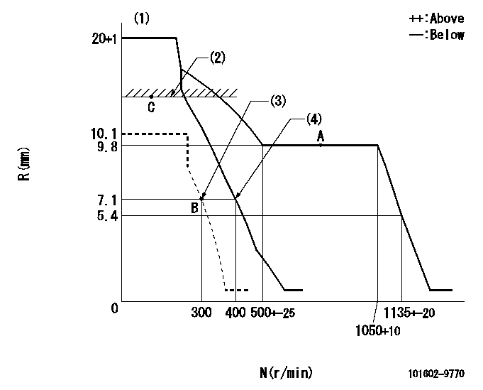
N:Pump speed
R:Rack position (mm)
(1)Target notch: K
(2)RACK LIMIT
(3)Set idle sub-spring
(4)Main spring setting
----------
K=18
----------
----------
K=18
----------
Speed control lever angle

F:Full speed
I:Idle
(1)Stopper bolt setting
----------
----------
a=(16deg)+-5deg b=(22deg)+-5deg
----------
----------
a=(16deg)+-5deg b=(22deg)+-5deg
Stop lever angle

N:Pump normal
S:Stop the pump.
----------
----------
a=26.5deg+-5deg b=53deg+-5deg
----------
----------
a=26.5deg+-5deg b=53deg+-5deg
Timing setting

(1)Pump vertical direction
(2)Coupling's key groove position at No 1 cylinder's beginning of injection
(3)B.T.D.C.: aa
(4)-
----------
aa=18deg
----------
a=(30deg)
----------
aa=18deg
----------
a=(30deg)
Information:
3. Install dowel (5) in governor shaft (6). Install the governor shaft in the carrier as shown. 4. Put the carrier in position on the camshaft. Install the bolts that hold the carrier in place.
Replace shield (7) with a new part any time it is removed.
5. Install shield (7) on the carrier, and use Tool (A) to push the shield against its seat. Use a hammer and punch to stake the metal in two places on the side of the shield 180° 5° apart next to the holes in the shield. 6. Install one race (9), bearing (10), the other race (9), and use Tool (B) to install the ring on riser (8) as shown. 7. Install riser (8) and the spring (overfueling spring) on the governor shaft as shown. 8. Assemble the dashpot as follows:a. Install spring (12) on seat (11). Install seat (13) in spring (12).b. Put spool (14) and ring (15) in position on seat (13). Use Tool (B) to install snap ring (16) to hold them in place. 9. Install dashpot assembly (17) on the governor shaft as shown. 10. Install ring (21) in the lower groove in the governor shaft. Install one sleeve (20), spring (19), the other sleeve (20) and bearing (18) on the governor shaft as shown. Spring (19) is used to put a preload on the thrust bearing on the camshaft in the fuel injection pump housing.11. Use Tool (C) to hold spring (19) under compression. Install ring (22) in the groove in the governor shaft. Remove Tool (C). 12. Put lever (27) in position on governor servo (23). Install pin (24) to hold the lever in place. Use a hammer and chisel to stake the metal four places 90° apart on the outside surface on both legs of the governor servo to hold pin (24) in place.13. Install the O-ring seal on sleeve (25). Install piston (26) and sleeve (25) in the governor servo as shown. 14. Install valve (28) in the governor servo as shown. 15. Install one lockring (32) in the groove near the center of valve (28). Put sleeve (29), spring (broken link spring) (30) and seat (31) in position on valve (28). Install the other lockring (32) to hold the components in place. 16. Put the governor servo in position on the fuel injection pump housing with piston (26) engaged over rack (33). Install the bolts that hold the governor servo in place. The 3306 Engine has two adjustment screws and lock nuts.17. Install torque rise adjustment screw (36) in collar (34) as shown. Install locknut (35) on the screw. 18. Install bolt (38) in block (40) as shown. Install spring (37) on bolt (38) as shown. Put collar (34) in position on bolt (38) with the hole in the collar