Information injection-pump assembly
ZEXEL
101602-9762
1016029762
MITSUBISHI-HEAV
3436100021
3436100021
Rating:
Cross reference number
ZEXEL
101602-9762
1016029762
MITSUBISHI-HEAV
3436100021
3436100021
Zexel num
Bosch num
Firm num
Name
Calibration Data:
Adjustment conditions
Test oil
1404 Test oil ISO4113 or {SAEJ967d}
1404 Test oil ISO4113 or {SAEJ967d}
Test oil temperature
degC
40
40
45
Nozzle and nozzle holder
105780-8140
Bosch type code
EF8511/9A
Nozzle
105780-0000
Bosch type code
DN12SD12T
Nozzle holder
105780-2080
Bosch type code
EF8511/9
Opening pressure
MPa
17.2
Opening pressure
kgf/cm2
175
Injection pipe
Outer diameter - inner diameter - length (mm) mm 6-2-600
Outer diameter - inner diameter - length (mm) mm 6-2-600
Overflow valve
131424-5720
Overflow valve opening pressure
kPa
255
221
289
Overflow valve opening pressure
kgf/cm2
2.6
2.25
2.95
Tester oil delivery pressure
kPa
157
157
157
Tester oil delivery pressure
kgf/cm2
1.6
1.6
1.6
Direction of rotation (viewed from drive side)
Right R
Right R
Injection timing adjustment
Direction of rotation (viewed from drive side)
Right R
Right R
Injection order
1-5-3-6-
2-4
Pre-stroke
mm
3.6
3.55
3.65
Beginning of injection position
Drive side NO.1
Drive side NO.1
Difference between angles 1
Cal 1-5 deg. 60 59.5 60.5
Cal 1-5 deg. 60 59.5 60.5
Difference between angles 2
Cal 1-3 deg. 120 119.5 120.5
Cal 1-3 deg. 120 119.5 120.5
Difference between angles 3
Cal 1-6 deg. 180 179.5 180.5
Cal 1-6 deg. 180 179.5 180.5
Difference between angles 4
Cyl.1-2 deg. 240 239.5 240.5
Cyl.1-2 deg. 240 239.5 240.5
Difference between angles 5
Cal 1-4 deg. 300 299.5 300.5
Cal 1-4 deg. 300 299.5 300.5
Injection quantity adjustment
Adjusting point
A
Rack position
8.4
Pump speed
r/min
900
900
900
Average injection quantity
mm3/st.
73.5
72.5
74.5
Max. variation between cylinders
%
0
-2.5
2.5
Basic
*
Fixing the lever
*
Injection quantity adjustment_02
Adjusting point
-
Rack position
6.9+-0.5
Pump speed
r/min
300
300
300
Average injection quantity
mm3/st.
12
10.7
13.3
Max. variation between cylinders
%
0
-14
14
Fixing the rack
*
Remarks
Adjust only variation between cylinders; adjust governor according to governor specifications.
Adjust only variation between cylinders; adjust governor according to governor specifications.
Injection quantity adjustment_03
Adjusting point
C
Rack position
-
Pump speed
r/min
100
100
100
Average injection quantity
mm3/st.
58
58
63
Fixing the lever
*
Rack limit
*
Test data Ex:
Governor adjustment
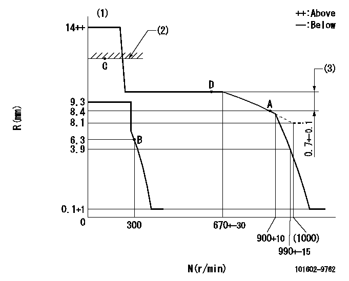
N:Pump speed
R:Rack position (mm)
(1)Target notch: K
(2)RACK LIMIT
(3)Rack difference between N = N1 and N = N2
----------
K=12 N1=900r/min N2=650r/min
----------
----------
K=12 N1=900r/min N2=650r/min
----------
Speed control lever angle

F:Full speed
I:Idle
(1)Stopper bolt setting
----------
----------
a=22deg+-5deg b=2deg+-5deg
----------
----------
a=22deg+-5deg b=2deg+-5deg
Stop lever angle

N:Pump normal
S:Stop the pump.
----------
----------
a=26.5deg+-5deg b=53deg+-5deg
----------
----------
a=26.5deg+-5deg b=53deg+-5deg
Timing setting

(1)Pump vertical direction
(2)Position of camshaft's key groove at No 1 cylinder's beginning of injection
(3)-
(4)-
----------
----------
a=(60deg)
----------
----------
a=(60deg)
Information:
1. Thoroughly clean the area around each fuel injection line connection before removal of any fuel injection lines. 2. Remove bolts (3) and (5) that fasten the mounting brackets to the cylinder head.3. Disconnect all fuel injection line nuts (2) at the fuel injection pump housing.
Do not let the tops of fuel injection nozzles (4) turn when fuel injection line nuts (6) are tightened. The nozzles will be damaged if the top of the nozzle turns in the body. The engine will be damaged if a defective fuel injection nozzle is used because the shape of fuel (spray pattern) that comes out of the nozzles will not be correct.
4. Use two wrenches, one to hold fuel injection nozzles (4) so they will not turn and one to disconnect fuel injection lines (1) from the nozzles.5. Remove fuel injection lines (1) from the engine. Put caps and plugs on the nozzles, fuel injection lines and fuel injection pump housing to keep dirt from entering the fuel system. The following steps are for installation of the fuel injection lines.6. Make sure the fuel injection lines are clean and dry.7. Put fuel injection lines (1) in position. Install all fuel injection line nuts (2) and (6) until they are finger tighten.8. Use a torque wrench and Tool (A) to tighten all fuel injection line nuts (2) to a torque of 41 7 N m (30 5 lb ft).
Do not let the tops of fuel injection nozzles (4) turn when the fuel injection lines are tightened. The nozzles will be damaged if the top of the nozzle turns in the body. The engine will be damaged if a defective fuel injection nozzle is used because the shape of fuel (spray pattern) that comes out of the nozzles will not be correct.
9. Use a wrench to hold fuel injection nozzles (4) so they will not turn. Use a torque wrench and Tool (A) to tighten all fuel injection line nuts (6) to a torque of 41 7 N m (30 5 lb ft).10. Install bolts (3) and (5) that fasten the mounting brackets to the cylinder head.11. Remove (bleed) the air from the fuel system. See the Operation & Maintenance Manual.