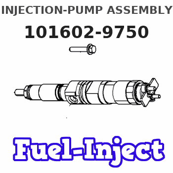
Information injection-pump assembly
ZEXEL
101602-9750
1016029750
NISSAN-DIESEL
1671295000
1671295000
Rating:
Service parts 101602-9750 INJECTION-PUMP ASSEMBLY:
1.
_
5.
AUTOM. ADVANCE MECHANIS
7.
COUPLING PLATE
8.
_
9.
_
11.
Nozzle and Holder
12.
Open Pre:MPa(Kqf/cm2)
19.6(200)
15.
NOZZLE SET
Include in #1:
101602-9750
as INJECTION-PUMP ASSEMBLY
Include in #2:
104742-1210
as _
Cross reference number
ZEXEL
101602-9750
1016029750
NISSAN-DIESEL
1671295000
1671295000
Zexel num
Bosch num
Firm num
Name
Calibration Data:
Adjustment conditions
Test oil
1404 Test oil ISO4113 or {SAEJ967d}
1404 Test oil ISO4113 or {SAEJ967d}
Test oil temperature
degC
40
40
45
Nozzle and nozzle holder
105780-8140
Bosch type code
EF8511/9A
Nozzle
105780-0000
Bosch type code
DN12SD12T
Nozzle holder
105780-2080
Bosch type code
EF8511/9
Opening pressure
MPa
17.2
Opening pressure
kgf/cm2
175
Injection pipe
Outer diameter - inner diameter - length (mm) mm 6-2-600
Outer diameter - inner diameter - length (mm) mm 6-2-600
Overflow valve
132424-0620
Overflow valve opening pressure
kPa
157
123
191
Overflow valve opening pressure
kgf/cm2
1.6
1.25
1.95
Tester oil delivery pressure
kPa
157
157
157
Tester oil delivery pressure
kgf/cm2
1.6
1.6
1.6
Direction of rotation (viewed from drive side)
Right R
Right R
Injection timing adjustment
Direction of rotation (viewed from drive side)
Right R
Right R
Injection order
1-4-2-6-
3-5
Pre-stroke
mm
2.75
2.7
2.8
Beginning of injection position
Drive side NO.1
Drive side NO.1
Difference between angles 1
Cal 1-4 deg. 60 59.5 60.5
Cal 1-4 deg. 60 59.5 60.5
Difference between angles 2
Cyl.1-2 deg. 120 119.5 120.5
Cyl.1-2 deg. 120 119.5 120.5
Difference between angles 3
Cal 1-6 deg. 180 179.5 180.5
Cal 1-6 deg. 180 179.5 180.5
Difference between angles 4
Cal 1-3 deg. 240 239.5 240.5
Cal 1-3 deg. 240 239.5 240.5
Difference between angles 5
Cal 1-5 deg. 300 299.5 300.5
Cal 1-5 deg. 300 299.5 300.5
Injection quantity adjustment
Adjusting point
A
Rack position
10.8
Pump speed
r/min
750
750
750
Average injection quantity
mm3/st.
106.8
105.3
108.3
Max. variation between cylinders
%
0
-2.5
2.5
Basic
*
Fixing the lever
*
Injection quantity adjustment_02
Adjusting point
C
Rack position
7.1+-0.5
Pump speed
r/min
300
300
300
Average injection quantity
mm3/st.
11.4
9.9
12.9
Max. variation between cylinders
%
0
-15
15
Fixing the rack
*
Test data Ex:
Governor adjustment
N:Pump speed
R:Rack position (mm)
(1)Target notch: K
(2)Rack difference between N = N1 and N = N2
----------
K=8 N1=750r/min N2=450r/min
----------
----------
K=8 N1=750r/min N2=450r/min
----------
Speed control lever angle
F:Full speed
I:Idle
(1)Set the pump speed at aa. ( At delivery )
(2)Set the pump speed at bb.
(3)Stopper bolt setting
----------
aa=900r/min bb=750r/min
----------
a=0deg+-5deg b=7deg+-5deg c=30deg+-5deg
----------
aa=900r/min bb=750r/min
----------
a=0deg+-5deg b=7deg+-5deg c=30deg+-5deg
Stop lever angle

N:Pump normal
S:Stop the pump.
----------
----------
a=26.5deg+-5deg b=53deg+-5deg
----------
----------
a=26.5deg+-5deg b=53deg+-5deg
0000001501 GOV FULL LOAD ADJUSTMENT
Title1:Full load stopper adjustment
Title2:Governor set speed
LABEL1:Distinguishing
LABEL2:Pump speed (r/min)
LABEL3:Ave. injection quantity (mm3/st)
LABEL4:Max. var. bet. cyl.
LABEL5:Remarks
LABEL6:Distinguishing
LABEL7:Governor set speed (r/min)
LABEL8:Remarks
(1)Adjustment conditions are the same as those for measuring injection quantity.
(2)-
----------
----------
a1=A a2=- r1=750r/min r2=- Q1=106.8+-1.5mm3/st Q2=- c1=+-2.5% c2=- a3=18 a4=15 r3=900r/min r4=750r/min
----------
----------
a1=A a2=- r1=750r/min r2=- Q1=106.8+-1.5mm3/st Q2=- c1=+-2.5% c2=- a3=18 a4=15 r3=900r/min r4=750r/min
Timing setting

(1)Pump vertical direction
(2)Coupling's key groove position at No 1 cylinder's beginning of injection
(3)B.T.D.C.: aa
(4)-
----------
aa=18deg
----------
a=(30deg)
----------
aa=18deg
----------
a=(30deg)
Information:
Problem
Some connecting rod assemblies may have been machined incorrectly. A machining discrepancy in the rod eye bore may not allow the rod eye bushing outside diameter to make complete contact with the rod eye bore. This can reduce the life of the bushing.
Affected Product
Model & Identification Number
3508 (7YG2069, 95Y1016, 96Y1725-1727, 23Z6865, 23Z6867-6871, 23Z6884-6885, 23Z6889, 23Z6892, 68Z903-906, 68Z909 , 68Z912, 68Z914, 69Z745-761)
3508B (7SM77, 7SM82-83)
G3508 (9TG141-144)
3512 (49Y835, 51Y760, 24Z7930-7932, 24Z7935-7948, 24Z7951, 24Z7953-7965, 24Z7969, 24Z7971, 24Z7980-7982, 24Z7985, 24Z7990-7991, 66Z718-721, 66Z1444-1445)
3512B (4TN99, 8RM201-202, 6WN137, 6FL145)
G3512 (7NJ287-290, 7NJ297)
3516 (5SJ542-543, 7CL416, 7CL419-421, 4XF673, 25Z5550-5551, 25Z5553-5555, 25Z5559, 25Z5567, 25Z5569-5574, 25Z5577, 25Z5584-5585, 28Z646, 29Z1227-1230, 67Z1447-1449)
3516B (9AN121, 8KN146-149, 8KN153-154, 7RN464-470)
G3516 (8LD46, 4EK1304-1305, 4EK1307-1313, 4EK1327, 4EK1334)
777D (3PR466-468, 3PR472-478, 3PR480)
Parts Needed
1 - 6I1356 Seal1 - 6I1357 Seal1 - 1013281 Rod Assembly1 - 1077330 Bearing (if necessary)1 - 1106991 Gasket-Head1 - 1106992 Gasket The parts are listed as one per failure. As many as 8, 12, or 16 parts may be required depending on the engine model. Additional parts not listed may be required depending on arrangement.
Action Required
See the attached procedure.
Owner Notification
U.S. and Canadian owners will receive the attached Owner Notification.
Service Claim Allowances
Labor Hour Breakdown For repairs of less than a complete set, 6.0 hours of labor per cylinder are reimbursable.
Allow 1.0 hour labor for testing of an engine and an additional 2.0 hours for setup/tear down.
The rod inspection, rod replacement and engine testing setup/tear down labor hours listed above are based on a basic 3500 Series Commercial Engine repaired in a dealer shop. Engines with various attachments, at customer sites or in a vehicle chassis may require additional labor hours. Those additional hours must be explained in the claim details.Costs incurred for emergency parts orders, for return of connecting rods, oil analysis, equipment needs to complete repairs or engine testing should be listed as other expenses and explained.
Parts Disposition
Return the removed defective connecting rod(s) to:
Caterpillar, Inc.
Attn: Jack Sanders - PI3047
Building B Claims Room
3701 State Road 26 East
Lafayette, Indiana 47905
Package the defective connecting rod(s) in it's original packaging carton for return shipment to Lafayette. Return defective parts within 24 hours of completion of removal from the engine. Call Matt Hannon at (765) 448-5138 or e-mail HANNOMJ with shipping Bill Number, part number, quantity in shipment, and Dealer name and location.
Dealers outside of North America should ship by Air Freight.
MAKE EVERY EFFORT TO COMPLETE THIS PROGRAM AS SOON AS POSSIBLE.
Attach.(1-Owner Notification)(2-Rework Procedure)Copy Of Owner Notification For U.S. And Canadian Owners
Rework Procedure
Connecting Rod Inspection
- The inspection of the connecting rod date code can be performed by removing the cylinder block side covers (left side typically most accessible) and viewing the date code. Rotation of the crankshaft and use of a mirror and a flash light will assist in viewing the date code on some rods. The date code is located on the side of the side of the rod cap at cap to rod joint. The date code format is YYMXXXX where (YY) is the year, (M) is a letter denoting the month, and (XXXX) is a sequence number. Rods with date