Information injection-pump assembly
ZEXEL
101602-9740
1016029740
NISSAN-DIESEL
1679095010
1679095010
Rating:
Service parts 101602-9740 INJECTION-PUMP ASSEMBLY:
1.
_
5.
AUTOM. ADVANCE MECHANIS
7.
COUPLING PLATE
8.
_
9.
_
11.
Nozzle and Holder
1660095004
12.
Open Pre:MPa(Kqf/cm2)
22.6(230)
15.
NOZZLE SET
Include in #1:
101602-9740
as INJECTION-PUMP ASSEMBLY
Include in #2:
104741-6670
as _
Cross reference number
ZEXEL
101602-9740
1016029740
NISSAN-DIESEL
1679095010
1679095010
Zexel num
Bosch num
Firm num
Name
101602-9740
1679095010 NISSAN-DIESEL
INJECTION-PUMP ASSEMBLY
NE6T * K
NE6T * K
Calibration Data:
Adjustment conditions
Test oil
1404 Test oil ISO4113 or {SAEJ967d}
1404 Test oil ISO4113 or {SAEJ967d}
Test oil temperature
degC
40
40
45
Nozzle and nozzle holder
105780-8140
Bosch type code
EF8511/9A
Nozzle
105780-0000
Bosch type code
DN12SD12T
Nozzle holder
105780-2080
Bosch type code
EF8511/9
Opening pressure
MPa
17.2
Opening pressure
kgf/cm2
175
Injection pipe
Outer diameter - inner diameter - length (mm) mm 6-2-600
Outer diameter - inner diameter - length (mm) mm 6-2-600
Tester oil delivery pressure
kPa
157
157
157
Tester oil delivery pressure
kgf/cm2
1.6
1.6
1.6
Direction of rotation (viewed from drive side)
Right R
Right R
Injection timing adjustment
Direction of rotation (viewed from drive side)
Right R
Right R
Injection order
1-4-2-6-
3-5
Pre-stroke
mm
2.75
2.7
2.8
Beginning of injection position
Drive side NO.1
Drive side NO.1
Difference between angles 1
Cal 1-4 deg. 60 59.5 60.5
Cal 1-4 deg. 60 59.5 60.5
Difference between angles 2
Cyl.1-2 deg. 120 119.5 120.5
Cyl.1-2 deg. 120 119.5 120.5
Difference between angles 3
Cal 1-6 deg. 180 179.5 180.5
Cal 1-6 deg. 180 179.5 180.5
Difference between angles 4
Cal 1-3 deg. 240 239.5 240.5
Cal 1-3 deg. 240 239.5 240.5
Difference between angles 5
Cal 1-5 deg. 300 299.5 300.5
Cal 1-5 deg. 300 299.5 300.5
Injection quantity adjustment
Adjusting point
A
Rack position
10
Pump speed
r/min
750
750
750
Average injection quantity
mm3/st.
82
80.5
83.5
Max. variation between cylinders
%
0
-2
2
Basic
*
Fixing the lever
*
Injection quantity adjustment_02
Adjusting point
B
Rack position
7.3+-0.5
Pump speed
r/min
300
300
300
Average injection quantity
mm3/st.
13
11.5
14.5
Max. variation between cylinders
%
0
-10
10
Fixing the rack
*
Injection quantity adjustment_03
Adjusting point
C
Rack position
-
Pump speed
r/min
100
100
100
Average injection quantity
mm3/st.
75
75
95
Fixing the lever
*
Rack limit
*
Test data Ex:
Governor adjustment
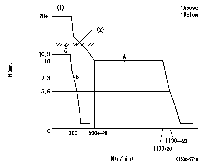
N:Pump speed
R:Rack position (mm)
(1)Target notch: K
(2)RACK LIMIT
----------
K=18
----------
----------
K=18
----------
Speed control lever angle

F:Full speed
I:Idle
(1)Stopper bolt setting
----------
----------
a=13deg+-5deg b=25deg+-5deg
----------
----------
a=13deg+-5deg b=25deg+-5deg
Stop lever angle
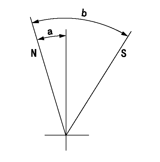
N:Pump normal
S:Stop the pump.
----------
----------
a=10.5deg+-5deg b=53deg+-5deg
----------
----------
a=10.5deg+-5deg b=53deg+-5deg
0000001501 GOV FULL LOAD ADJUSTMENT

Title1:Full load stopper adjustment
Title2:Governor set speed
LABEL1:Distinguishing
LABEL2:Pump speed (r/min)
LABEL3:Ave. injection quantity (mm3/st)
LABEL4:Max. var. bet. cyl.
LABEL5:Remarks
LABEL6:Distinguishing
LABEL7:Governor set speed (r/min)
LABEL8:Maximum no-load speed (r/min)
LABEL9:Remarks
(1)Adjustment conditions are the same as those for measuring injection quantity.
(2)At high idle rack position L
----------
L=5.6mm
----------
a1=B a2=- a3=- a4=- r1=750r/min r2=- r3=- r4=- Q1=82+-1.5mm3/st Q2=- Q3=- Q4=- c1=+-2% c2=- c3=- c4=- a5=22 a6=21 a7=20 a8=19 a9=18 a10=17 a11=16 a12=15 a13=14 a14=- a15=- r5=1100r/min r6=1050r/min r7=1000r/min r8=950r/min r9=900r/min r10=850r/min r11=800r/min r12=750r/min r13=700r/min r14=- r15=- R5=1180+-27r/min R6=1130+-26r/min R7=1075+-25r/min R8=1020+-23r/min R9=965+-22r/min R10=915+-22r/min R11=860+-20r/min R12=805+-18r/min R13=750+-17r/min R14=- R15=-
----------
L=5.6mm
----------
a1=B a2=- a3=- a4=- r1=750r/min r2=- r3=- r4=- Q1=82+-1.5mm3/st Q2=- Q3=- Q4=- c1=+-2% c2=- c3=- c4=- a5=22 a6=21 a7=20 a8=19 a9=18 a10=17 a11=16 a12=15 a13=14 a14=- a15=- r5=1100r/min r6=1050r/min r7=1000r/min r8=950r/min r9=900r/min r10=850r/min r11=800r/min r12=750r/min r13=700r/min r14=- r15=- R5=1180+-27r/min R6=1130+-26r/min R7=1075+-25r/min R8=1020+-23r/min R9=965+-22r/min R10=915+-22r/min R11=860+-20r/min R12=805+-18r/min R13=750+-17r/min R14=- R15=-
Timing setting

(1)Pump vertical direction
(2)Coupling's key groove position at No 1 cylinder's beginning of injection
(3)B.T.D.C.: aa
(4)-
----------
aa=18deg
----------
a=(30deg)
----------
aa=18deg
----------
a=(30deg)
Information:
The information supplied in this service letter may not be valid after the termination date of this program. Do not perform the work outlined in this Service Letter after the termination date without first contacting your Caterpillar product analyst.
Termination Date
August 31, 1997Problem
0R0906, 0R1756, 0R1758, 0R2921, 0R2922, 0R2923, 0R2924, 0R2925, 0R3051, and 0R3052 Remanufactured Unit Injectors with date codes between January 01, 1997 and April 30, 1997 need to be removed from Parts Stock.Action Required
Inspect all 0R0906, 0R1756, 0R1758, 0R2921, 0R2922, 0R2923, 0R2924, 0R2925, 0R3051, and 0R3052 Remanufactured Unit Injectors with date codes between January 01, 1997 and April 30, 1997 from Parts Stock.
The date code can be located below the part name and above the part number on part number tag attached to the box. The date code is formatted as DDMMYYXXX (example; a box marked with a date code of 150195068 would indicate a part manufactured on January 15, 1995 at plant number 068).
If the injector is no longer in the original box, use the date code engraved on the top of the unit injector tappet. It is in the "NUMERAL KOD" format. The code consists of the month and the year.
Where the numbers for the months and years are coded as follows:
January 1997 ... NUDKFebruary 1997... NMDKMarch 1997 ... NEDKApril 1997 ... NRDKTo inspect the injectors, push the rack bar in against the trim adjustment screw (the fuel off position). On the flat "D" section of the rack bar extending out of the injector and beyond the rack teeth, inspect for a shinny grooved machine mark completely across the flat surface and parallel with the rack teeth. This mark is caused by the plunger gear contacting the flat of the rack bar If the mark is present, the injector should be returned to Caterpillar.
Service Claim Allowances
Submit one claim for all 0R0906, 0R1756, 0R1758, 0R2921, 0R2922, 0R2923, 0R2924, 0R2925, 0R3051, and 0R3052 Remanufactured Unit Injectors with date codes between January 01, 1997 and April 30, 1997 removed from Parts Stock.
MEPS dealers are reimbursed for recalled Parts Stock by returning the affected Parts Stock to their administering Caterpillar dealer for replacement.
Parts Disposition
All injectors removed from Parts Stock are to be returned as cores for remanufacturing.
U.S. and Canadian Dealers
Return all 0R0906, 0R1756, 0R1758, 0R2921, 0R2922, 0R2923, 0R2924, 0R2925, 0R3051, and 0R3052 Remanufactured Unit Injectors with date codes between January 01, 1997 and April 30, 1997 that are removed from Parts Stock and a copy of the claim to:
Caterpillar Inc.
Attn: Bill Harland - Warranty Review
501 Cardinal Drive
Corinth, MS 38834
All Other Dealers
Handle the parts in accordance with your Warranty Bulletin on Remanufactured Engines and Components, refer to the topic "Disposition of the Core Under Warranty".
Have questions with 101602-9740?
Group cross 101602-9740 ZEXEL
Yanmar
Nissan-Diesel
Nissan-Diesel
101602-9740
1679095010
INJECTION-PUMP ASSEMBLY
NE6T
NE6T