Information injection-pump assembly
ZEXEL
101602-9641
1016029641
NISSAN-DIESEL
16790Z5569
16790z5569
Rating:
Service parts 101602-9641 INJECTION-PUMP ASSEMBLY:
1.
_
5.
AUTOM. ADVANCE MECHANIS
7.
COUPLING PLATE
8.
_
9.
_
11.
Nozzle and Holder
16600Z5511
12.
Open Pre:MPa(Kqf/cm2)
19.6(200)
15.
NOZZLE SET
Include in #1:
101602-9641
as INJECTION-PUMP ASSEMBLY
Include in #2:
104741-6631
as _
Cross reference number
ZEXEL
101602-9641
1016029641
NISSAN-DIESEL
16790Z5569
16790z5569
Zexel num
Bosch num
Firm num
Name
101602-9641
16790Z5569 NISSAN-DIESEL
INJECTION-PUMP ASSEMBLY
FD6 * K
FD6 * K
Calibration Data:
Adjustment conditions
Test oil
1404 Test oil ISO4113 or {SAEJ967d}
1404 Test oil ISO4113 or {SAEJ967d}
Test oil temperature
degC
40
40
45
Nozzle and nozzle holder
105780-8140
Bosch type code
EF8511/9A
Nozzle
105780-0000
Bosch type code
DN12SD12T
Nozzle holder
105780-2080
Bosch type code
EF8511/9
Opening pressure
MPa
17.2
Opening pressure
kgf/cm2
175
Injection pipe
Outer diameter - inner diameter - length (mm) mm 6-2-600
Outer diameter - inner diameter - length (mm) mm 6-2-600
Overflow valve opening pressure
kPa
157
123
191
Overflow valve opening pressure
kgf/cm2
1.6
1.25
1.95
Tester oil delivery pressure
kPa
157
157
157
Tester oil delivery pressure
kgf/cm2
1.6
1.6
1.6
Direction of rotation (viewed from drive side)
Right R
Right R
Injection timing adjustment
Direction of rotation (viewed from drive side)
Right R
Right R
Injection order
1-4-2-6-
3-5
Pre-stroke
mm
3
2.95
3.05
Beginning of injection position
Drive side NO.1
Drive side NO.1
Difference between angles 1
Cal 1-4 deg. 60 59.5 60.5
Cal 1-4 deg. 60 59.5 60.5
Difference between angles 2
Cyl.1-2 deg. 120 119.5 120.5
Cyl.1-2 deg. 120 119.5 120.5
Difference between angles 3
Cal 1-6 deg. 180 179.5 180.5
Cal 1-6 deg. 180 179.5 180.5
Difference between angles 4
Cal 1-3 deg. 240 239.5 240.5
Cal 1-3 deg. 240 239.5 240.5
Difference between angles 5
Cal 1-5 deg. 300 299.5 300.5
Cal 1-5 deg. 300 299.5 300.5
Injection quantity adjustment
Adjusting point
A
Rack position
9
Pump speed
r/min
750
750
750
Average injection quantity
mm3/st.
44.7
43.1
46.3
Max. variation between cylinders
%
0
-2
2
Basic
*
Fixing the lever
*
Injection quantity adjustment_02
Adjusting point
B
Rack position
7.5+-0.5
Pump speed
r/min
300
300
300
Average injection quantity
mm3/st.
8.2
6.4
10
Max. variation between cylinders
%
0
-12
12
Fixing the rack
*
Test data Ex:
Governor adjustment
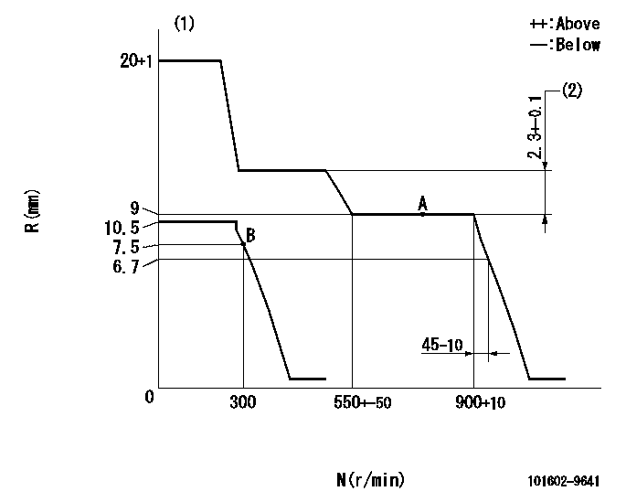
N:Pump speed
R:Rack position (mm)
(1)Target notch: K
(2)Rack difference between N = N1 and N = N2
----------
K=10 N1=750r/min N2=400r/min
----------
----------
K=10 N1=750r/min N2=400r/min
----------
Speed control lever angle

F:Full speed
I:Idle
(1)Stopper bolt setting
----------
----------
a=(3deg)+-5deg b=(21deg)+-5deg
----------
----------
a=(3deg)+-5deg b=(21deg)+-5deg
Stop lever angle

N:Pump normal
S:Stop the pump.
----------
----------
a=26.5deg+-5deg b=53deg+-5deg
----------
----------
a=26.5deg+-5deg b=53deg+-5deg
Timing setting

(1)Pump vertical direction
(2)Position of coupling's threaded hole at No 1 cylinder's beginning of injection
(3)-
(4)-
----------
----------
a=(60deg)
----------
----------
a=(60deg)
Information:
Termination Date
January 31, 1993Problem
The fuel injection pumps used on certain Remanufactured 1160 and 3208 Engines need to be inspected for gummy deposits.
Affected Product
Model & Identification Number
1160 (57V1-34325)
3208 (9WC1-730; 5CD1-5868; 62W1-68596; 93Z1-8374)
Remanufactured Fuel Pump Part Numbers
0R07660R09030R23840R23860R09020R23740R23850R2877 The above list of remanufactured pumps are affected only if they are stamped with a date code of 12/91 (UMDU) or earlier.
Parts Needed
Not Applicable
Action Required
Before installing or delivering any of the affected product, perform the following steps to ensure the internal fuel injection pump components are not stuck due to fuel pump gumming:
1. Remove the top cover of the fuel injection pump and check to ensure that all sleeves and levers are free and there are no gummy deposits on any of these components.2. If inspection performed in Step 1 indicates everything is clean, install top cover and return to parts stock.3. If inspection reveals components have gummy deposits, remove 12 ounces of fuel from the fuel pump housing and replace it with: - Fuel Injector Cleaner or
- Carburetor/Choke Cleaner
4. Allow the components to soak in cleaning solution for 45 minutes, then rotate the engine crankshaft to rotate the fuel injection pump (on pumps only, rotate the fuel pump camshaft). This will ensure the components have the gummy deposits removed. If the engine or fuel pump will be used immediately, install the cover on the fuel injection pump, and install or deliver the engine or pump.5. If the engine or fuel pump will be returned to stock, DO NOT leave the fuel injection pump full of cleaning solution because it may not contain any rust inhibitors. Remove the cleaning solution, fill the fuel injector pump with clean diesel fuel, and install the cover on the pump.Service Claim Allowances
It is a .5-hr. job to inspect the pump. An additional .5-hr. may be claimed if cleaning is required.
Parts Disposition
Handle the parts in accordance with your Warranty Bulletin on warranty parts handling.
Have questions with 101602-9641?
Group cross 101602-9641 ZEXEL
Nissan-Diesel
Daewoo
Nissan-Diesel
101602-9641
16790Z5569
INJECTION-PUMP ASSEMBLY
FD6
FD6