Information injection-pump assembly
ZEXEL
101602-9450
1016029450

Rating:
Cross reference number
ZEXEL
101602-9450
1016029450
Zexel num
Bosch num
Firm num
Name
Calibration Data:
Adjustment conditions
Test oil
1404 Test oil ISO4113 or {SAEJ967d}
1404 Test oil ISO4113 or {SAEJ967d}
Test oil temperature
degC
40
40
45
Nozzle and nozzle holder
105780-8140
Bosch type code
EF8511/9A
Nozzle
105780-0000
Bosch type code
DN12SD12T
Nozzle holder
105780-2080
Bosch type code
EF8511/9
Opening pressure
MPa
17.2
Opening pressure
kgf/cm2
175
Injection pipe
Outer diameter - inner diameter - length (mm) mm 6-2-600
Outer diameter - inner diameter - length (mm) mm 6-2-600
Overflow valve
132424-0620
Overflow valve opening pressure
kPa
157
123
191
Overflow valve opening pressure
kgf/cm2
1.6
1.25
1.95
Tester oil delivery pressure
kPa
157
157
157
Tester oil delivery pressure
kgf/cm2
1.6
1.6
1.6
Direction of rotation (viewed from drive side)
Right R
Right R
Injection timing adjustment
Direction of rotation (viewed from drive side)
Right R
Right R
Injection order
1-4-2-6-
3-5
Pre-stroke
mm
3
2.95
3.05
Beginning of injection position
Drive side NO.1
Drive side NO.1
Difference between angles 1
Cal 1-4 deg. 60 59.5 60.5
Cal 1-4 deg. 60 59.5 60.5
Difference between angles 2
Cyl.1-2 deg. 120 119.5 120.5
Cyl.1-2 deg. 120 119.5 120.5
Difference between angles 3
Cal 1-6 deg. 180 179.5 180.5
Cal 1-6 deg. 180 179.5 180.5
Difference between angles 4
Cal 1-3 deg. 240 239.5 240.5
Cal 1-3 deg. 240 239.5 240.5
Difference between angles 5
Cal 1-5 deg. 300 299.5 300.5
Cal 1-5 deg. 300 299.5 300.5
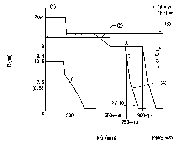
Injection quantity adjustment
Adjusting point
A
Rack position
9
Pump speed
r/min
750
750
750
Average injection quantity
mm3/st.
44.7
43.1
46.3
Max. variation between cylinders
%
0
-2
2
Basic
*
Fixing the lever
*
Injection quantity adjustment_02
Adjusting point
B
Rack position
8.4
Pump speed
r/min
750
750
750
Average injection quantity
mm3/st.
37.5
35.9
39.1
Max. variation between cylinders
%
0
-3
3
Fixing the rack
*
Injection quantity adjustment_03
Adjusting point
C
Rack position
7.5+-0.5
Pump speed
r/min
300
300
300
Average injection quantity
mm3/st.
8.2
6.4
10
Max. variation between cylinders
%
0
-12
12
Fixing the rack
*
Test data Ex:
Governor adjustment
N:Pump speed
R:Rack position (mm)
(1)Target notch: K
(2)RACK LIMIT: RAL
(3)Rack difference between N = N1 and N = N2
(4)Standard injection quantity Q = QL
----------
K=16 RAL=10.4+0.2mm N1=900r/min N2=400r/min QL=12mm3/st
----------
----------
K=16 RAL=10.4+0.2mm N1=900r/min N2=400r/min QL=12mm3/st
----------
Speed control lever angle
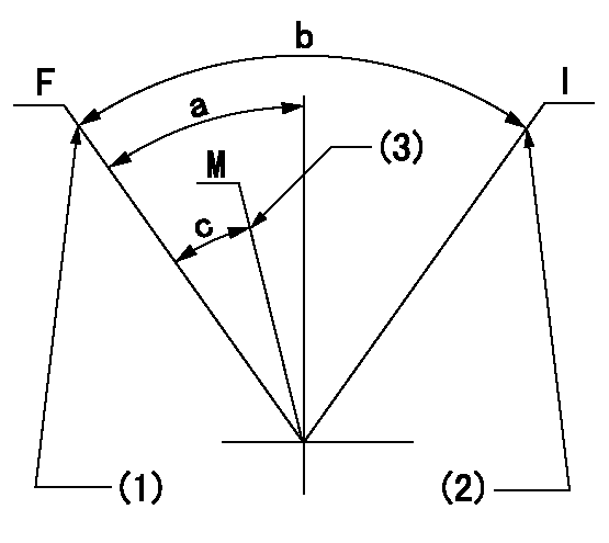
F:Full speed
I:Idle
M:Minimum-maximum speed
(1)Set the pump speed at aa. (At delivery)
(2)Stopper bolt setting
(3)Pump speed = bb
----------
aa=900r/min bb=750r/min
----------
a=(10deg)+-5deg b=(20deg)+-5deg c=(5deg)+-5deg
----------
aa=900r/min bb=750r/min
----------
a=(10deg)+-5deg b=(20deg)+-5deg c=(5deg)+-5deg
Stop lever angle

N:Pump normal
S:Stop the pump.
----------
----------
a=26deg+-5deg b=53deg+-5deg
----------
----------
a=26deg+-5deg b=53deg+-5deg
0000001501 GOV FULL LOAD ADJUSTMENT
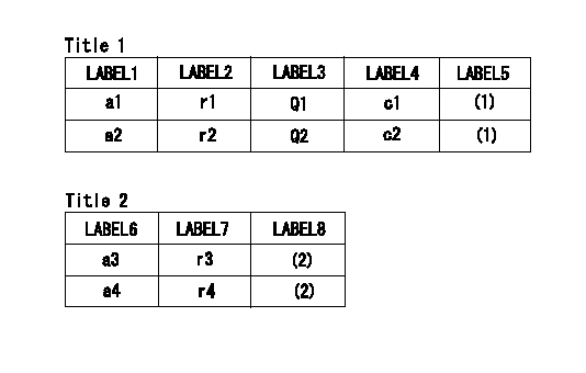
Title1:Full load stopper adjustment
Title2:Governor set speed
LABEL1:Distinguishing
LABEL2:Pump speed (r/min)
LABEL3:Ave. injection quantity (mm3/st)
LABEL4:Max. var. bet. cyl.
LABEL5:Remarks
LABEL6:Distinguishing
LABEL7:Governor set speed (r/min)
LABEL8:Remarks
(1)Adjustment conditions are the same as those for measuring injection quantity.
(2)-
----------
----------
a1=A a2=B r1=750r/min r2=750r/min Q1=48.2+-1.6mm3/st Q2=44.7+-1.6mm3/st c1=+-2% c2=+-2% a3=18 a4=15 r3=900r/min r4=750r/min
----------
----------
a1=A a2=B r1=750r/min r2=750r/min Q1=48.2+-1.6mm3/st Q2=44.7+-1.6mm3/st c1=+-2% c2=+-2% a3=18 a4=15 r3=900r/min r4=750r/min
Timing setting

(1)Pump vertical direction
(2)Coupling's key groove position at No 1 cylinder's beginning of injection
(3)-
(4)-
----------
----------
a=(30deg)
----------
----------
a=(30deg)
Information:
(1) Outer spring: Length under test force ... 27.4 mm (1.08 in.)Test force ... 180 9 N (40 2 lb.)Free length after test ... 45.2 mm (1.78 in.)(Damper coils of spring go toward cylinder head.)(2) Inner spring: Length under test force ... 23.88 mm (.940 in.)Test force ... 69 9 N (15.4 2 lb.)Free length after test ... 39.6 mm (1.56 in.)(Damper coils of spring go toward cylinder head.)(3) Valve guides: Inside diameter ... 9.507 to 9.543 mm (.3743 to .3757 in.)Outside diameter ... 15.921 to 15.933 mm (.6268 to .6273 in.)Parent bore diameter in cylinder head for valve guide ... 15.867 to 15.893 mm (.6247 to .6257 in.)Interference fit of guide in cylinder head ... 0.028 to 0.066 mm (.0011 to .0026 in.)Overall length of guide: Intake ... 57.94 mm (2.281 in.)Exhaust ... 61.11 mm (2.406 in.)Projection of guide above valve spring recess ... 15.09 mm (.594 in.)(4) Intake valve: Valve stem diameter ... 9.42 to 9.45 mm (.371 to .372 in.)Clearance of valve in guide ... 0.058 to 0.119 mm (.0023 to .0047 in.)Maximum permissible clearance of valve in guide ... 0.13 mm (.005 in.)Valve head diameter ... 44.09 to 44.35 mm (1.736 to 1.746 in.) Grinding angles: Valve face angle ... 45°Valve seat angle ... 45°Valve head depth below cylinder head face: Minimum ... 1.02 mm (.040 in.)Maximum ... 1.27 mm (.050 in.)Service wear limit ... 1.52 mm (.060 in.)Overall length of valve ... 122.71 to 123.11 mm (4.831 to 4.847 in.)(5) Exhaust valve: Valve stem diameter ... 9.42 to 9.45 mm (.371 to .372 in.)Clearance of valve in guide ... 0.058 to 0.119 mm (.0023 to .0047 in.)Maximum permissible clearance of valve in guide (all models) ... 0.15 mm (.006 in.)Valve head diameter ... 37.26 to 37.52 mm (1.467 to 1.477 in.)Grinding angles: Valve face angle ... 45°Valve seat angle ... 45°Valve head depth below cylinder head face: Minimum ... 1.02 mm (.040 in.)Maximum ... 1.27 mm (.050 in.)Service wear limit ... 1.52 mm (.060 in.)Overall length of valve ... 123.11 to 123.52 mm (4.847 to 4.863 in.)(6) Maximum permissible depth of bore to grind the flare of the valve seat ... 2.69 to 2.79 mm (.106 to .110 in.)(7) Angle to grind flare of valve seat ... 33° (8) Use the dimensions that follow to machine the recess into the cylinder head for valve seat inserts not already installed in the head. Intake: A ... 7.19 to 7.32 mm (.283 to .288 in.)B ... 51.219 to 51.245 mm (2.0165 to 2.0175 in.)C (Radius) ... 0.38 mm (.015 in.)Exhaust: A ... 9.53 to 9.65 mm (.375 to .380 in.)B ... 42.62 to 42.65 mm (1.678 to 1.679 in.)C (Radius) ... 0.38 mm (.015 in.)