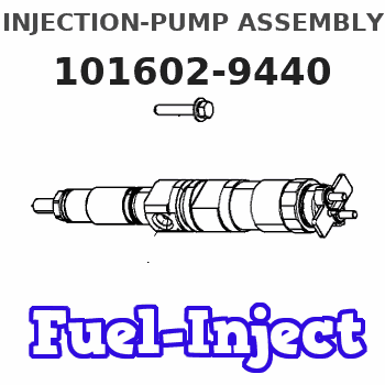
Information injection-pump assembly
ZEXEL
101602-9440
1016029440
Rating:
Cross reference number
ZEXEL
101602-9440
1016029440
Zexel num
Bosch num
Firm num
Name
Calibration Data:
Adjustment conditions
Test oil
1404 Test oil ISO4113 or {SAEJ967d}
1404 Test oil ISO4113 or {SAEJ967d}
Test oil temperature
degC
40
40
45
Nozzle and nozzle holder
105780-8140
Bosch type code
EF8511/9A
Nozzle
105780-0000
Bosch type code
DN12SD12T
Nozzle holder
105780-2080
Bosch type code
EF8511/9
Opening pressure
MPa
17.2
Opening pressure
kgf/cm2
175
Injection pipe
Outer diameter - inner diameter - length (mm) mm 6-2-600
Outer diameter - inner diameter - length (mm) mm 6-2-600
Overflow valve
132424-0620
Overflow valve opening pressure
kPa
157
123
191
Overflow valve opening pressure
kgf/cm2
1.6
1.25
1.95
Tester oil delivery pressure
kPa
157
157
157
Tester oil delivery pressure
kgf/cm2
1.6
1.6
1.6
Direction of rotation (viewed from drive side)
Right R
Right R
Injection timing adjustment
Direction of rotation (viewed from drive side)
Right R
Right R
Injection order
1-4-2-6-
3-5
Pre-stroke
mm
3
2.95
3.05
Beginning of injection position
Drive side NO.1
Drive side NO.1
Difference between angles 1
Cal 1-4 deg. 60 59.5 60.5
Cal 1-4 deg. 60 59.5 60.5
Difference between angles 2
Cyl.1-2 deg. 120 119.5 120.5
Cyl.1-2 deg. 120 119.5 120.5
Difference between angles 3
Cal 1-6 deg. 180 179.5 180.5
Cal 1-6 deg. 180 179.5 180.5
Difference between angles 4
Cal 1-3 deg. 240 239.5 240.5
Cal 1-3 deg. 240 239.5 240.5
Difference between angles 5
Cal 1-5 deg. 300 299.5 300.5
Cal 1-5 deg. 300 299.5 300.5
Injection quantity adjustment
Adjusting point
A
Rack position
9.8
Pump speed
r/min
750
750
750
Average injection quantity
mm3/st.
61.1
59.5
62.7
Max. variation between cylinders
%
0
-2
2
Basic
*
Fixing the lever
*
Injection quantity adjustment_02
Adjusting point
B
Rack position
9.3
Pump speed
r/min
750
750
750
Average injection quantity
mm3/st.
51.4
49.8
53
Max. variation between cylinders
%
0
-3
3
Fixing the rack
*
Injection quantity adjustment_03
Adjusting point
C
Rack position
8.1+-0.5
Pump speed
r/min
300
300
300
Average injection quantity
mm3/st.
9.5
7.7
11.3
Max. variation between cylinders
%
0
-12
12
Fixing the rack
*
Remarks
Adjust only variation between cylinders; adjust governor according to governor specifications.
Adjust only variation between cylinders; adjust governor according to governor specifications.
Test data Ex:
Governor adjustment
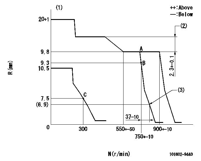
N:Pump speed
R:Rack position (mm)
(1)Target notch: K
(2)Rack difference between N = N1 and N = N2
(3)Injection quantity Q = Q1
----------
K=13 N1=900r/min N2=400r/min Q1=14mm3/st
----------
----------
K=13 N1=900r/min N2=400r/min Q1=14mm3/st
----------
Speed control lever angle
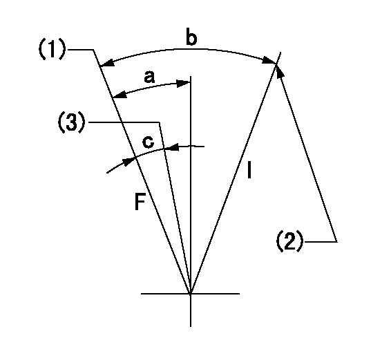
F:Full speed
I:Idle
(1)Set the pump speed at aa. ( At delivery )
(2)Stopper bolt setting
(3)Set the pump speed at bb.
----------
aa=900r/min bb=750r/min
----------
a=(9deg)+-5deg b=(21deg)+-5deg c=(5deg)+-5deg
----------
aa=900r/min bb=750r/min
----------
a=(9deg)+-5deg b=(21deg)+-5deg c=(5deg)+-5deg
Stop lever angle

N:Pump normal
S:Stop the pump.
----------
----------
a=26deg+-5deg b=53deg+-5deg
----------
----------
a=26deg+-5deg b=53deg+-5deg
Timing setting

(1)Pump vertical direction
(2)Coupling's key groove position at No 1 cylinder's beginning of injection
(3)-
(4)-
----------
----------
a=(30deg)
----------
----------
a=(30deg)
Information:
Lubrication System
OIL LUBRICATION SCHEMATICThe lubrication system is the pressure type. The oil pump draws oil from the sump through a suction pipe and strainer to the pump. The oil pump is driven by the auxiliary drive group which is driven by the timing gears.Pressure oil flows to the oil cooler. The oil cooler is cooled by water from the cooling system. Coolers on T6.3544 Engines have a bypass valve that allows the oil to go around the cooler in case of a restriction or if the oil is too cold and thick. From the cooler, oil passes through the relief valve. On T6.3544 Engines, the relief valve is two stage. At 205 to 225 kPa (30 to 37 psi), oil is fed by a pipe to the piston cooling jet gallery which is a drilled passage the length of the crankcase, above the camshaft chamber. The piston cooling jets are bolted into the gallery and point into the bottom of each cylinder. Oil is sprayed onto the underneath side of each piston which takes heat from the combustion area. The oil then drains back to sump.At 345 to 415 kPa (50 to 60 psi), oil passes through a single oil filter on 6.3544 Engines or two filters on T6.3544 Engines. Oil then flows to the main oil gallery which is a drilled passage the length of the crankcase. Oil also flows from the filters to the turbocharger bearings on T6.3544 Engines. Passages in the crankcase webs feed oil from the main oil gallery to the main bearings. Passages in the crankshaft carry oil to the big end bearings. Through passages in No. 1, 3, 5 and 7 crankcase webs, oil passes from the main bearings to lubricate the camshaft bearings.The No. 2 camshaft bearing supplies a controlled amount of oil to the rocker shaft assembly, which then flows through a small bleed hole in each rocker lever to lubricate the valves and springs.Pistons, cylinder liners, connecting rod small end bushings, cam lobes and valve lifters are splash and oil mist lubricated.Oil flows from the main oil gallery to the two idler gear hubs. The oil passes through the hubs to radial passages in the idler gears to lubricate the teeth of the timing gears.The auxiliary drive group shaft bearings are lubricated by a passage from the main oil gallery to the front auxiliary drive shaft bearing. Oil then passes around a groove in the bearing journal and through another passage along the outer side of the auxiliary drive housing to the rear auxiliary drive shaft bearing. The upper fuel pump bearing is also lubricated from this passage. Also connected to this outer housing passage is a spray tube which directs oil on to the auxiliary drive shaft (worn gear) and gear assembly (worm wheel).Air Inlet And Exhaust System
6.3544 Engines
AIR INLET AND EXHAUST SYSTEM COMPONENTS
1. Exhaust manifold. 2. Inlet manifold. 3. Engine cylinderThe air inlet and exhaust system components on naturally aspirated engines are: the air cleaner, inlet manifold,