Information injection-pump assembly
ZEXEL
101602-9410
1016029410
Rating:
Cross reference number
ZEXEL
101602-9410
1016029410
Zexel num
Bosch num
Firm num
Name
Calibration Data:
Adjustment conditions
Test oil
1404 Test oil ISO4113 or {SAEJ967d}
1404 Test oil ISO4113 or {SAEJ967d}
Test oil temperature
degC
40
40
45
Nozzle and nozzle holder
105780-8140
Bosch type code
EF8511/9A
Nozzle
105780-0000
Bosch type code
DN12SD12T
Nozzle holder
105780-2080
Bosch type code
EF8511/9
Opening pressure
MPa
17.2
Opening pressure
kgf/cm2
175
Injection pipe
Outer diameter - inner diameter - length (mm) mm 6-2-600
Outer diameter - inner diameter - length (mm) mm 6-2-600
Overflow valve
132424-0620
Overflow valve opening pressure
kPa
157
123
191
Overflow valve opening pressure
kgf/cm2
1.6
1.25
1.95
Tester oil delivery pressure
kPa
157
157
157
Tester oil delivery pressure
kgf/cm2
1.6
1.6
1.6
Direction of rotation (viewed from drive side)
Right R
Right R
Injection timing adjustment
Direction of rotation (viewed from drive side)
Right R
Right R
Injection order
1-4-2-6-
3-5
Pre-stroke
mm
3
2.95
3.05
Beginning of injection position
Drive side NO.1
Drive side NO.1
Difference between angles 1
Cal 1-4 deg. 60 59.5 60.5
Cal 1-4 deg. 60 59.5 60.5
Difference between angles 2
Cyl.1-2 deg. 120 119.5 120.5
Cyl.1-2 deg. 120 119.5 120.5
Difference between angles 3
Cal 1-6 deg. 180 179.5 180.5
Cal 1-6 deg. 180 179.5 180.5
Difference between angles 4
Cal 1-3 deg. 240 239.5 240.5
Cal 1-3 deg. 240 239.5 240.5
Difference between angles 5
Cal 1-5 deg. 300 299.5 300.5
Cal 1-5 deg. 300 299.5 300.5
Injection quantity adjustment
Adjusting point
A
Rack position
9.5
Pump speed
r/min
900
900
900
Average injection quantity
mm3/st.
73.2
72.2
74.2
Max. variation between cylinders
%
0
-5
5
Fixing the lever
*
Boost pressure
kPa
14.7
14.7
Boost pressure
mmHg
110
110
Injection quantity adjustment_02
Adjusting point
B
Rack position
9.3
Pump speed
r/min
600
600
600
Average injection quantity
mm3/st.
55
54
56
Max. variation between cylinders
%
0
-3.5
3.5
Basic
*
Fixing the lever
*
Boost pressure
kPa
14.7
14.7
Boost pressure
mmHg
110
110
Injection quantity adjustment_03
Adjusting point
C
Rack position
8.7
Pump speed
r/min
600
600
600
Average injection quantity
mm3/st.
42.6
40.6
44.6
Max. variation between cylinders
%
0
-5
5
Fixing the lever
*
Boost pressure
kPa
0
0
0
Boost pressure
mmHg
0
0
0
Injection quantity adjustment_04
Adjusting point
D
Rack position
7.8+-0.5
Pump speed
r/min
290
290
290
Average injection quantity
mm3/st.
9.5
7.7
11.3
Max. variation between cylinders
%
0
-10
10
Fixing the rack
*
Boost pressure
kPa
0
0
0
Boost pressure
mmHg
0
0
0
Remarks
Adjust only variation between cylinders; adjust governor according to governor specifications.
Adjust only variation between cylinders; adjust governor according to governor specifications.
Injection quantity adjustment_05
Adjusting point
E
Rack position
-
Pump speed
r/min
100
100
100
Average injection quantity
mm3/st.
57
57
Fixing the lever
*
Boost pressure
kPa
0
0
0
Boost pressure
mmHg
0
0
0
Boost compensator adjustment
Pump speed
r/min
600
600
600
Rack position
8.7
Boost pressure
kPa
4
4
4
Boost pressure
mmHg
30
30
30
Boost compensator adjustment_02
Pump speed
r/min
600
600
600
Rack position
9.3
Boost pressure
kPa
6.7
5.4
8
Boost pressure
mmHg
50
40
60
Test data Ex:
Governor adjustment
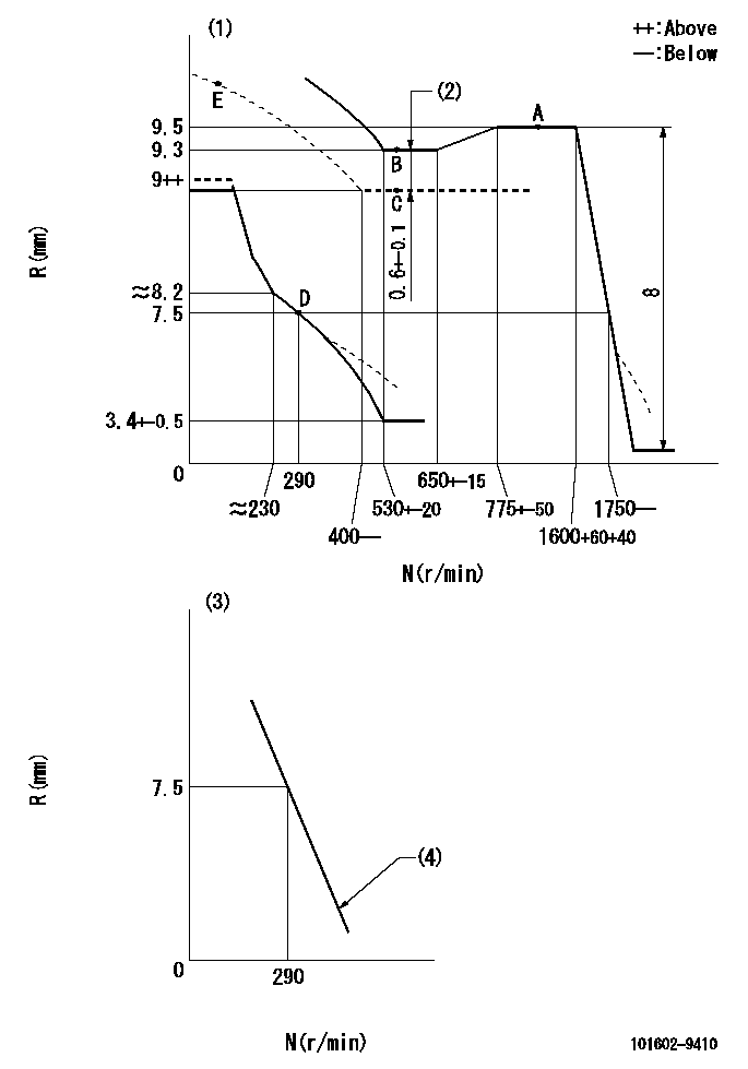
N:Pump speed
R:Rack position (mm)
(1)Beginning of damper spring operation: DL
(2)Boost compensator stroke
(3)Variable speed specification: idling adjustment
(4)Main spring setting
----------
DL=6.5-0.2mm
----------
----------
DL=6.5-0.2mm
----------
Speed control lever angle
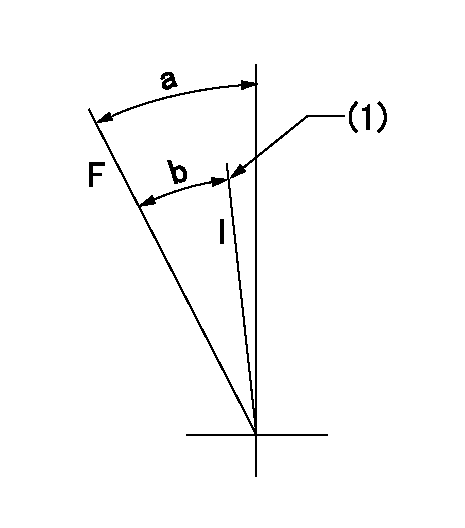
F:Full speed
I:Idle
(1)Stopper bolt setting
----------
----------
a=22deg+-5deg b=(18deg)
----------
----------
a=22deg+-5deg b=(18deg)
0000000901

F:Full load
I:Idle
(1)Stopper bolt setting
----------
----------
a=19deg+-5deg b=22deg+-3deg
----------
----------
a=19deg+-5deg b=22deg+-3deg
Stop lever angle

N:Pump normal
S:Stop the pump.
----------
----------
a=45deg+-5deg b=71deg+-5deg
----------
----------
a=45deg+-5deg b=71deg+-5deg
Timing setting

(1)Pump vertical direction
(2)Coupling's key groove position at No 1 cylinder's beginning of injection
(3)-
(4)-
----------
----------
a=(30deg)
----------
----------
a=(30deg)
Information:
Typical 12 Volt Starting Circuit
(1) Test point. (2) Test point. (3) Test Point. (4) Test Point. (5) Test Point. (X) Hold-in coil. (W) Pull-in coil.General Information
All starting systems are made up of four elements. They are the ignition switch, start relay, the starting motor solenoid and starting motor. The only exception to this is that on some small engines the start relay may not be required. In this case, the start switch powers the starting motor solenoid directly.Start switches are relatively low current devices. They are rated to switch approximately 5 to 20 amps. Because the coil of a start relay [between test point (1) and (2)] draws about 1 amp, the start switch can easily turn on the start relay and have long life.The switch contacts of a typical start relay are rated to switch between 100 and 300 amps. Because the solenoid requires 5 to 50 amps, the start relay can easily switch this load.The starting motor solenoid has two functions: 1) it engages the pinion with the flywheel, and 2) it is a high current switch rated about 1000 amps that actually turns on the starting motor.The starting motor solenoid has two coils. Pull-in coil (W) draws about 40 amps and hold-in coil (X) requires about 5 amps. The instant the start relay closes, both coils (W) and (X) receive power. Battery voltage is applied to the high end of both coils, at test point (3) which is the start (S) terminal. The low end of hold-in coil (X) is permanently grounded to the ground post or motor housing of the starting motor. Grounding for the low end, test point (4), of pull-in coil (W) is momentary, and takes place through the DC resistance of the starting motor. As soon as magnetic force builds in both coils, the pinion moves toward the flywheel ring gear. The pinion will stop short of engagement of the flywheel ring gear. Only then will the solenoid contacts close to power the starting motor. This temporarily removes the ground from pull-in coil (W), and puts battery voltage on both ends of it while the starting motor cranks. During this period, the pull-in coil is out of the circuit. Cranking continues until power to the solenoid is broken by releasing the ignition switch.The result of these switches and relays is to permit a 5 amp dash-mounted switch to turn on a 500 to 1000 amp motor used to crank an engine.Battery voltage (power) available during cranking varies according to the temperature of the batteries. The following chart is a guide as to what to expect from a normal system. The next chart shows maximum acceptable voltage loss in the high current battery circuit feeding the starting motor. These values are maximums for machines of approximately 2000 SMH and up. Newer machines would be less than those shown. Voltages greater than those shown are most often caused by loose and/or corroded connections or defective switch contacts.Diagnosis Procedure
Do not operate the starting motor