Information injection-pump assembly
ZEXEL
101602-9390
1016029390

Rating:
Cross reference number
ZEXEL
101602-9390
1016029390
Zexel num
Bosch num
Firm num
Name
Calibration Data:
Adjustment conditions
Test oil
1404 Test oil ISO4113 or {SAEJ967d}
1404 Test oil ISO4113 or {SAEJ967d}
Test oil temperature
degC
40
40
45
Nozzle and nozzle holder
105780-8140
Bosch type code
EF8511/9A
Nozzle
105780-0000
Bosch type code
DN12SD12T
Nozzle holder
105780-2080
Bosch type code
EF8511/9
Opening pressure
MPa
17.2
Opening pressure
kgf/cm2
175
Injection pipe
Outer diameter - inner diameter - length (mm) mm 6-2-600
Outer diameter - inner diameter - length (mm) mm 6-2-600
Overflow valve
132424-0620
Overflow valve opening pressure
kPa
157
123
191
Overflow valve opening pressure
kgf/cm2
1.6
1.25
1.95
Tester oil delivery pressure
kPa
157
157
157
Tester oil delivery pressure
kgf/cm2
1.6
1.6
1.6
Direction of rotation (viewed from drive side)
Right R
Right R
Injection timing adjustment
Direction of rotation (viewed from drive side)
Right R
Right R
Injection order
1-4-2-6-
3-5
Pre-stroke
mm
3
2.95
3.05
Beginning of injection position
Drive side NO.1
Drive side NO.1
Difference between angles 1
Cal 1-4 deg. 60 59.5 60.5
Cal 1-4 deg. 60 59.5 60.5
Difference between angles 2
Cyl.1-2 deg. 120 119.5 120.5
Cyl.1-2 deg. 120 119.5 120.5
Difference between angles 3
Cal 1-6 deg. 180 179.5 180.5
Cal 1-6 deg. 180 179.5 180.5
Difference between angles 4
Cal 1-3 deg. 240 239.5 240.5
Cal 1-3 deg. 240 239.5 240.5
Difference between angles 5
Cal 1-5 deg. 300 299.5 300.5
Cal 1-5 deg. 300 299.5 300.5
Injection quantity adjustment
Adjusting point
A
Rack position
9.5
Pump speed
r/min
900
900
900
Average injection quantity
mm3/st.
73.2
72.2
74.2
Max. variation between cylinders
%
0
-5
5
Fixing the lever
*
Boost pressure
kPa
14.7
14.7
Boost pressure
mmHg
110
110
Injection quantity adjustment_02
Adjusting point
B
Rack position
9.3
Pump speed
r/min
600
600
600
Average injection quantity
mm3/st.
55
54
56
Max. variation between cylinders
%
0
-3.5
3.5
Basic
*
Fixing the lever
*
Boost pressure
kPa
14.7
14.7
Boost pressure
mmHg
110
110
Injection quantity adjustment_03
Adjusting point
C
Rack position
8.7
Pump speed
r/min
600
600
600
Average injection quantity
mm3/st.
42.6
40.6
44.6
Max. variation between cylinders
%
0
-5
5
Fixing the lever
*
Boost pressure
kPa
0
0
0
Boost pressure
mmHg
0
0
0
Injection quantity adjustment_04
Adjusting point
D
Rack position
7.8+-0.5
Pump speed
r/min
290
290
290
Average injection quantity
mm3/st.
9.5
7.7
11.3
Max. variation between cylinders
%
0
-10
10
Fixing the rack
*
Boost pressure
kPa
0
0
0
Boost pressure
mmHg
0
0
0
Remarks
Adjust only variation between cylinders; adjust governor according to governor specifications.
Adjust only variation between cylinders; adjust governor according to governor specifications.
Injection quantity adjustment_05
Adjusting point
E
Rack position
-
Pump speed
r/min
100
100
100
Average injection quantity
mm3/st.
57
57
Fixing the lever
*
Boost pressure
kPa
0
0
0
Boost pressure
mmHg
0
0
0
Boost compensator adjustment
Pump speed
r/min
600
600
600
Rack position
8.7
Boost pressure
kPa
4
4
4
Boost pressure
mmHg
30
30
30
Boost compensator adjustment_02
Pump speed
r/min
600
600
600
Rack position
9.3
Boost pressure
kPa
6.7
5.4
8
Boost pressure
mmHg
50
40
60
Test data Ex:
Governor adjustment
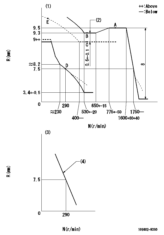
N:Pump speed
R:Rack position (mm)
(1)Beginning of damper spring operation: DL
(2)Boost compensator stroke
(3)Variable speed specification: idling adjustment
(4)Main spring setting
----------
DL=6.5-0.2mm
----------
----------
DL=6.5-0.2mm
----------
Speed control lever angle
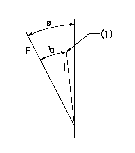
F:Full speed
I:Idle
(1)Stopper bolt setting
----------
----------
a=22deg+-5deg b=(18deg)
----------
----------
a=22deg+-5deg b=(18deg)
0000000901

F:Full load
I:Idle
(1)Stopper bolt setting
----------
----------
a=19deg+-5deg b=22deg+-3deg
----------
----------
a=19deg+-5deg b=22deg+-3deg
Stop lever angle

N:Pump normal
S:Stop the pump.
(1)Use the pin at R = aa
----------
aa=20mm
----------
a=40deg+-5deg b=71deg+-5deg
----------
aa=20mm
----------
a=40deg+-5deg b=71deg+-5deg
Timing setting

(1)Pump vertical direction
(2)Coupling's key groove position at No 1 cylinder's beginning of injection
(3)-
(4)-
----------
----------
a=(30deg)
----------
----------
a=(30deg)
Information:
4.236 Engines(1) First (top) compression ring: Width of compression ring ... 2.362 to 2.375 mm (.0930 to .0935 in)Clearance between ends of ring installed in cylinder liner that has no wear ... 0.25 to 0.56 mm (.010 to .022 in)(2) Second compression ring: Width of compression ring ... 2.362 to 2.375 mm (.0930 to .0935 in)Clearance between ends of each ring installed in cylinder liner that has no wear ... 0.20 to 0.56 mm (.008 to .022 in)(3) Oil ring: Width of oil ring ... 4.724 to 4.737 mm (.1860 to .1865 in)Clearance between ends of each ring installed in cylinder liner that has no wear ... 0.25 to 0.53 mm (.010 to .021 in)(4) Width of groove for first compression ring ... 2.46 to 2.49 mm (.097 to .098 in) Ring clearance in the groove ... 0.089 to 0.127 mm (.0035 to .0050 in)(5) Width of groove for second compression ring ... 2.44 to 2.46 mm (.096 to .097 in) Ring clearance in the groove ... 0.064 to 0.102 mm (.0025 to .0040 in)(6) Width of groove for oil ring ... 4.788 to 4.806 mm (.1885 to .1892 in) Ring clearance in the groove ... 0.051 to 0.081 mm (.0020 to .0032 in)(7) Bore in piston for pin ... 34.9212 to 34.9263 mm (1.37485 to 1.37505 in) Diameter of piston pin (new) ... 34.920 to 34.93 mm (1.3748 to 1.375 in)Piston height above cylinder block (not shown) ... 0.36 to 0.58 mm (.014 to .023 in)C4.236 Engines
C4.236 Engines(1) First (top) compression ring: Width of compression ring ... wedge shapedClearance between ends of ring installed in cylinder liner that has no wear ... 0.25 to 0.61 mm (.010 to .024 in)(2) Second compression ring: Width of compression ring ... 2.362 to 2.375 mm (.0930 to .0935 in)Clearance between ends of each ring installed in cylinder liner that has no wear ... 0.25 to 0.69 mm (.010 to .027 in)(3) Oil ring: Width of oil ring ... 4.724 to 4.763 mm (.1860 to .1875 in)Clearance between ends of each ring installed in cylinder liner that has no wear ... 0.25 to 0.79 mm (.010 to .031 in)(4) Width of groove for first compression ring ... tapered(5) Width of groove for second compression ring ... 2.426 to 2.446 mm (.0955 to .0963 in) Ring clearance in the groove ... 0.051 to 0.084 mm (.0020 to .0033 in)(6) Width of groove for oil ring ... 4.788 to 4.808 mm (.1885 to .1893 in) Ring clearance in the groove ... 0.025 to 0.084 mm (.0010 to .0033 in)(7) Bore in piston for pin ... 38.100 to 38.1005 mm (1.5000 to 1.50002 in) Diameter of piston pin (new) ... 38.095 to 38.100 mm (1.4998 to 1.5000 in)Piston height above cylinder block (not shown) ... 0.36 to 0.58 mm (.014 to .023 in)