Information injection-pump assembly
ZEXEL
101602-9380
1016029380

Rating:
Cross reference number
ZEXEL
101602-9380
1016029380
Zexel num
Bosch num
Firm num
Name
Calibration Data:
Adjustment conditions
Test oil
1404 Test oil ISO4113 or {SAEJ967d}
1404 Test oil ISO4113 or {SAEJ967d}
Test oil temperature
degC
40
40
45
Nozzle and nozzle holder
105780-8140
Bosch type code
EF8511/9A
Nozzle
105780-0000
Bosch type code
DN12SD12T
Nozzle holder
105780-2080
Bosch type code
EF8511/9
Opening pressure
MPa
17.2
Opening pressure
kgf/cm2
175
Injection pipe
Outer diameter - inner diameter - length (mm) mm 6-2-600
Outer diameter - inner diameter - length (mm) mm 6-2-600
Overflow valve opening pressure
kPa
157
123
191
Overflow valve opening pressure
kgf/cm2
1.6
1.25
1.95
Tester oil delivery pressure
kPa
157
157
157
Tester oil delivery pressure
kgf/cm2
1.6
1.6
1.6
Direction of rotation (viewed from drive side)
Right R
Right R
Injection timing adjustment
Direction of rotation (viewed from drive side)
Right R
Right R
Injection order
1-4-2-6-
3-5
Pre-stroke
mm
3
2.95
3.05
Beginning of injection position
Drive side NO.1
Drive side NO.1
Difference between angles 1
Cal 1-4 deg. 60 59.5 60.5
Cal 1-4 deg. 60 59.5 60.5
Difference between angles 2
Cyl.1-2 deg. 120 119.5 120.5
Cyl.1-2 deg. 120 119.5 120.5
Difference between angles 3
Cal 1-6 deg. 180 179.5 180.5
Cal 1-6 deg. 180 179.5 180.5
Difference between angles 4
Cal 1-3 deg. 240 239.5 240.5
Cal 1-3 deg. 240 239.5 240.5
Difference between angles 5
Cal 1-5 deg. 300 299.5 300.5
Cal 1-5 deg. 300 299.5 300.5
Injection quantity adjustment
Adjusting point
A
Rack position
9.5
Pump speed
r/min
900
900
900
Average injection quantity
mm3/st.
73.2
72.2
74.2
Max. variation between cylinders
%
0
-5
5
Fixing the lever
*
Boost pressure
kPa
14.7
14.7
Boost pressure
mmHg
110
110
Injection quantity adjustment_02
Adjusting point
B
Rack position
9.3
Pump speed
r/min
600
600
600
Average injection quantity
mm3/st.
55
54
56
Max. variation between cylinders
%
0
-3.5
3.5
Basic
*
Fixing the lever
*
Boost pressure
kPa
14.7
14.7
Boost pressure
mmHg
110
110
Injection quantity adjustment_03
Adjusting point
C
Rack position
8.7
Pump speed
r/min
600
600
600
Average injection quantity
mm3/st.
42.6
40.6
44.6
Max. variation between cylinders
%
0
-5
5
Fixing the lever
*
Boost pressure
kPa
0
0
0
Boost pressure
mmHg
0
0
0
Injection quantity adjustment_04
Adjusting point
D
Rack position
7.8+-0.5
Pump speed
r/min
290
290
290
Average injection quantity
mm3/st.
9.5
7.7
11.3
Max. variation between cylinders
%
0
-10
10
Fixing the rack
*
Boost pressure
kPa
0
0
0
Boost pressure
mmHg
0
0
0
Remarks
Adjust only variation between cylinders; adjust governor according to governor specifications.
Adjust only variation between cylinders; adjust governor according to governor specifications.
Injection quantity adjustment_05
Adjusting point
E
Rack position
-
Pump speed
r/min
100
100
100
Average injection quantity
mm3/st.
57
57
Fixing the lever
*
Boost pressure
kPa
0
0
0
Boost pressure
mmHg
0
0
0
Boost compensator adjustment
Pump speed
r/min
600
600
600
Rack position
8.7
Boost pressure
kPa
4
4
4
Boost pressure
mmHg
30
30
30
Boost compensator adjustment_02
Pump speed
r/min
600
600
600
Rack position
9.3
Boost pressure
kPa
6.7
5.4
8
Boost pressure
mmHg
50
40
60
Test data Ex:
Governor adjustment
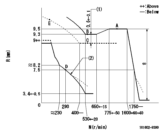
N:Pump speed
R:Rack position (mm)
(1)Boost compensator stroke
(2)Beginning of damper spring operation: DL
----------
DL=6.5-0.2mm
----------
----------
DL=6.5-0.2mm
----------
0000000901

F:Full load
I:Idle
(1)Stopper bolt setting
----------
----------
a=19deg+-5deg b=22deg+-3deg
----------
----------
a=19deg+-5deg b=22deg+-3deg
Stop lever angle

N:Pump normal
S:Stop the pump.
(1)Use the pin at R = aa
----------
aa=20mm
----------
a=40deg+-5deg b=71deg+-5deg
----------
aa=20mm
----------
a=40deg+-5deg b=71deg+-5deg
Timing setting

(1)Pump vertical direction
(2)Coupling's key groove position at No 1 cylinder's beginning of injection
(3)-
(4)-
----------
----------
a=(30deg)
----------
----------
a=(30deg)
Information:
Earlier Engines
(1) Cylinder head bolts and nuts tightening procedure:1. Put engine oil on the threads of bolts and nuts. Tighten all bolts and nuts in number sequence to a torque of ... 45 N m (35 lb ft)2. Tighten all bolts and nuts in number sequence to a torque of ... 95 N m (70 lb ft)3. Again tighten all bolts and nuts in number sequence to a final torque of 135 N m (100 lb ft).Retighten the cylinder head bolts and nuts after the engine has run under part load for approximately thirty minutes.a. If the bolts and nuts move before the correct final torque is reached, retighten everything in the sequence again to the final torque of 135 N m (100 lb ft).b. If the bolts and nuts do not move before the correct final torque is reached, back each one off 30 to 60° (with an 8T3052 Degree Wheel) and retighten again, in the sequence shown, to the final torque. After all the bolts and nuts are retightened, check the first 10 positions to make sure they are tightened to the correct torque.c. After 25 to 50 hours of service for a new or rebuilt engine, retorque the cylinder head bolts as shown in Step a above and adjust the valves again. New cylinder blocks have been introduced on the 4.236 engine for the Backhoe Loaders. The new cylinder blocks have deeper cylinder head bolt holes and longer bolts. The old and new sizes are shown. The change became effective at engine serial number LD70178U027631M and UP. The engine serial number is located above the fuel injection pump on the block. The new cylinder head bolts are not interchangeable between old and new blocks. All other models will have the new arrangement at first production.Later Engines
New cylinder heads have been introduced on the 4.236 engine for the Backhoe Loaders. The new 4P4722 Cylinder Head is used with a 7C3191 Head Gasket and uses a new cylinder head torque procedure. The change became effective at engine serial number LD70178U419182U and UP. The change is adaptable to engines serial number LD70178U106654N and UP. The engine serial number is located above the fuel injection pump on the block.(1) Cylinder head bolts tightening procedure:a. Check the head bolts for any distortion with a straight edge along the threads. If there is a visual reduction in the thread diameter of any threads that have not been in engagement with the cylinder block, the bolt must be replaced.b. Put engine oil on the threads of bolts. Tighten all bolts in number sequence to a torque of ... 45 N m (35 lb ft).c. Tighten all bolts in number sequence to a torque of ... 95 N m (70 lb ft).d. Again tighten all bolts and nuts in number sequence to a torque of ... 120 N m (88 lb ft).e. Turn each bolt (with an 8T3052 Degree Wheel) in number sequence an additional