Information injection-pump assembly
ZEXEL
101602-9300
1016029300
YANMAR
12765351010
12765351010
Rating:
Cross reference number
ZEXEL
101602-9300
1016029300
YANMAR
12765351010
12765351010
Zexel num
Bosch num
Firm num
Name
Calibration Data:
Adjustment conditions
Test oil
1404 Test oil ISO4113 or {SAEJ967d}
1404 Test oil ISO4113 or {SAEJ967d}
Test oil temperature
degC
40
40
45
Nozzle and nozzle holder
105780-8140
Bosch type code
EF8511/9A
Nozzle
105780-0000
Bosch type code
DN12SD12T
Nozzle holder
105780-2080
Bosch type code
EF8511/9
Opening pressure
MPa
17.2
Opening pressure
kgf/cm2
175
Injection pipe
Outer diameter - inner diameter - length (mm) mm 6-2-600
Outer diameter - inner diameter - length (mm) mm 6-2-600
Overflow valve
132424-0620
Overflow valve opening pressure
kPa
157
123
191
Overflow valve opening pressure
kgf/cm2
1.6
1.25
1.95
Tester oil delivery pressure
kPa
157
157
157
Tester oil delivery pressure
kgf/cm2
1.6
1.6
1.6
Direction of rotation (viewed from drive side)
Right R
Right R
Injection timing adjustment
Direction of rotation (viewed from drive side)
Right R
Right R
Injection order
1-4-2-6-
3-5
Pre-stroke
mm
3.8
3.75
3.85
Beginning of injection position
Drive side NO.1
Drive side NO.1
Difference between angles 1
Cal 1-4 deg. 60 59.5 60.5
Cal 1-4 deg. 60 59.5 60.5
Difference between angles 2
Cyl.1-2 deg. 120 119.5 120.5
Cyl.1-2 deg. 120 119.5 120.5
Difference between angles 3
Cal 1-6 deg. 180 179.5 180.5
Cal 1-6 deg. 180 179.5 180.5
Difference between angles 4
Cal 1-3 deg. 240 239.5 240.5
Cal 1-3 deg. 240 239.5 240.5
Difference between angles 5
Cal 1-5 deg. 300 299.5 300.5
Cal 1-5 deg. 300 299.5 300.5
Injection quantity adjustment
Adjusting point
A
Rack position
11.6
Pump speed
r/min
900
900
900
Each cylinder's injection qty
mm3/st.
72
70.6
73.4
Basic
*
Fixing the rack
*
Injection quantity adjustment_02
Adjusting point
B
Rack position
9.2+-0.5
Pump speed
r/min
300
300
300
Each cylinder's injection qty
mm3/st.
10
9
11
Fixing the rack
*
Injection quantity adjustment_03
Adjusting point
C
Rack position
-
Pump speed
r/min
100
100
100
Each cylinder's injection qty
mm3/st.
140
140
170
Fixing the lever
*
Rack limit
*
Test data Ex:
Governor adjustment
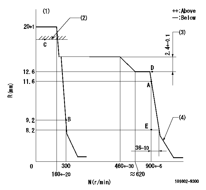
N:Pump speed
R:Rack position (mm)
(1)Target notch: K
(2)RACK LIMIT
(3)Rack difference between N = N1 and N = N2
(4)Idle sub spring setting: L1.
----------
K=10 N1=800r/min N2=400r/min L1=7.7-0.5mm
----------
----------
K=10 N1=800r/min N2=400r/min L1=7.7-0.5mm
----------
Speed control lever angle
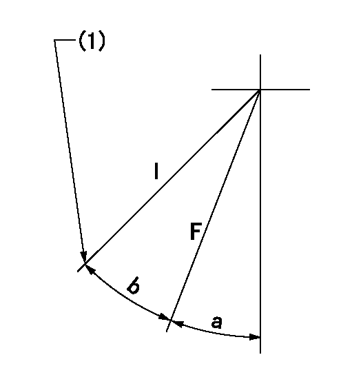
F:Full speed
I:Idle
(1)Stopper bolt setting
----------
----------
a=4deg+-5deg b=20deg+-5deg
----------
----------
a=4deg+-5deg b=20deg+-5deg
Stop lever angle

N:Pump normal
S:Stop the pump.
----------
----------
a=20deg+-5deg b=53deg+-5deg
----------
----------
a=20deg+-5deg b=53deg+-5deg
Information:
ACTION REQUIRED
Refer to the attached Rework Procedure.
OWNER NOTIFICATION
U.S. and Canadian owners will receive the attached Owner Notification.
SERVICE CLAIM ALLOWANCES
Caterpillar Dealer Suggested Customer Suggested
Parts % Labor Hrs% Parts % Labor Hrs% Parts % Labor Hrs%
100% 100% 0% 0% 0% 0%
This is a 4.0-hour job
PARTS DISPOSITION
Handle the parts in accordance with your Warranty Bulletin on warranty parts handling.
MAKE EVERY EFFORT TO COMPLETE THIS PROGRAM AS SOON AS POSSIBLE.
COPY OF OWNER NOTIFICATION FOR U.S. AND CANADIAN OWNERS
XYZ Corporation
3240 Arrow Drive
Anywhere, YZ 99999
PRIORITY - PRODUCT IMPROVEMENT PROGRAM FOR REPLACING THE DIESEL PARTICULATE FILTER ON CERTAIN SKID STEER LOADERS AND COMPACT TRACK LOADERS
MODELS INVOLVED - 272D Skid Steer Loaders and 299D Compact Track Loaders
Dear Cat Product Owner:
The diesel particulate filter needs to be replaced on certain 272D Skid Steer Loaders and 299D Compact Track Loaders. The existing diesel particulate filter has been installed incorrectly which can result in decreased performance of the filter. You will not be charged for the service performed.
Contact your local Cat dealer immediately to schedule this service. The dealer will advise you of the time required to complete this service.
Please refer the dealer to their Service Letter dated 06Aug2012 when scheduling this service.
We regret the inconvenience this may cause you, but urge you to have this service performed as soon as possible to prevent unscheduled downtime.
Caterpillar Inc.
Identification #(s)
Attached to 06Aug2012 Service Letter
Rework Procedure
1. Remove the cooling package. Refer UENR2328, Disassembly and Assembly, "Radiator and Hydraulic Oil Cooler - Removal Procedure".
2. Record the diesel particulate filter serial number prior to installing. The serial number is etched into the diesel particulate filter housing in the location shown in Image1.1.1. It is the lower set of digits. Send the new diesel particulate filter serial number and machine serial number to Rob McHardy (MCHARDY_ROBERT_W).
Image1.1.1
Image1.1.2
3. Replace the 389-5370 Diesel Particulate Filter section. Refer to UENR0129, Disassembly and Assembly, "Diesel Particulate Filter - Remove and Install" and "Diesel Particulate Filter - Disassemble".
4. When performing this work, replace the three 389-5373 Gaskets (metal) for the diesel particulate filter section and the 345-3579 Gasket between the turbo flange and the DOC inlet.
5. Ensure the diesel particulate filter is installed with the exhaust flowing in the direction of the arrow that is on the diesel particulate filter. Refer to Image1.2.1.
6. Cover both ends of the diesel particulate filter to ensure the ash and soot remain within the diesel particulate filter. Package the diesel particulate filter according to REHS3827, "Procedure to Handle and Ship Diesel Particulate Filters (DPF) and Catalytic Converter Mufflers (CCM)".
7. Connect Caterpillar Electronic Technician (ET). Version 2012A is acceptable but version 2012B is recommended. Go to Service Tab and select "DPF Soot Load Reset". At the next two screens select the "Reset" button in the bottom left corner.
Image1.2.1