Information injection-pump assembly
BOSCH
9 400 610 632
9400610632
ZEXEL
101602-9141
1016029141
YANMAR
12665051041
12665051041

Rating:
Service parts 101602-9141 INJECTION-PUMP ASSEMBLY:
1.
_
5.
AUTOM. ADVANCE MECHANIS
6.
COUPLING PLATE
7.
COUPLING PLATE
8.
_
9.
_
10.
NOZZLE AND HOLDER ASSY
11.
Nozzle and Holder
12.
Open Pre:MPa(Kqf/cm2)
13.
NOZZLE-HOLDER
14.
NOZZLE
15.
NOZZLE SET
Cross reference number
BOSCH
9 400 610 632
9400610632
ZEXEL
101602-9141
1016029141
YANMAR
12665051041
12665051041
Zexel num
Bosch num
Firm num
Name
101602-9141
9 400 610 632
12665051041 YANMAR
INJECTION-PUMP ASSEMBLY
6HAL K 14BE INJECTION PUMP ASSY PE6A PE
6HAL K 14BE INJECTION PUMP ASSY PE6A PE
Calibration Data:
Adjustment conditions
Test oil
1404 Test oil ISO4113 or {SAEJ967d}
1404 Test oil ISO4113 or {SAEJ967d}
Test oil temperature
degC
40
40
45
Nozzle and nozzle holder
105780-8140
Bosch type code
EF8511/9A
Nozzle
105780-0000
Bosch type code
DN12SD12T
Nozzle holder
105780-2080
Bosch type code
EF8511/9
Opening pressure
MPa
17.2
Opening pressure
kgf/cm2
175
Injection pipe
Outer diameter - inner diameter - length (mm) mm 6-2-600
Outer diameter - inner diameter - length (mm) mm 6-2-600
Overflow valve
132424-0620
Overflow valve opening pressure
kPa
157
123
191
Overflow valve opening pressure
kgf/cm2
1.6
1.25
1.95
Tester oil delivery pressure
kPa
157
157
157
Tester oil delivery pressure
kgf/cm2
1.6
1.6
1.6
Direction of rotation (viewed from drive side)
Right R
Right R
Injection timing adjustment
Direction of rotation (viewed from drive side)
Right R
Right R
Injection order
1-4-2-6-
3-5
Pre-stroke
mm
2.7
2.65
2.75
Beginning of injection position
Drive side NO.1
Drive side NO.1
Difference between angles 1
Cal 1-4 deg. 60 59.5 60.5
Cal 1-4 deg. 60 59.5 60.5
Difference between angles 2
Cyl.1-2 deg. 120 119.5 120.5
Cyl.1-2 deg. 120 119.5 120.5
Difference between angles 3
Cal 1-6 deg. 180 179.5 180.5
Cal 1-6 deg. 180 179.5 180.5
Difference between angles 4
Cal 1-3 deg. 240 239.5 240.5
Cal 1-3 deg. 240 239.5 240.5
Difference between angles 5
Cal 1-5 deg. 300 299.5 300.5
Cal 1-5 deg. 300 299.5 300.5
Injection quantity adjustment
Adjusting point
A
Rack position
12.7
Pump speed
r/min
900
900
900
Each cylinder's injection qty
mm3/st.
121
118.6
123.4
Basic
*
Fixing the rack
*
Injection quantity adjustment_02
Adjusting point
B
Rack position
7.5+-0.5
Pump speed
r/min
250
250
250
Each cylinder's injection qty
mm3/st.
15
13.5
16.5
Fixing the rack
*
Test data Ex:
Governor adjustment
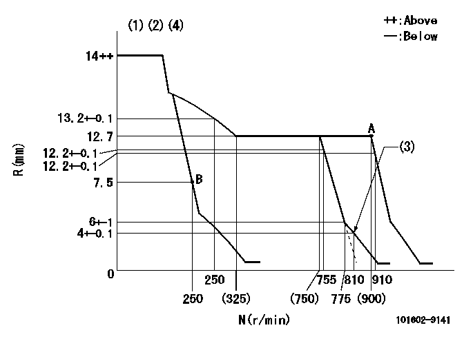
N:Pump speed
R:Rack position (mm)
(1)Target notch: K
(2)Tolerance for racks not indicated: +-0.05mm.
(3)Set idle sub-spring
(4)Confirm that the rack is pulled back to R = R1 or less at solenoid operation (N = N1).
----------
K=13 R1=5.5mm N1=700r/min
----------
----------
K=13 R1=5.5mm N1=700r/min
----------
Speed control lever angle
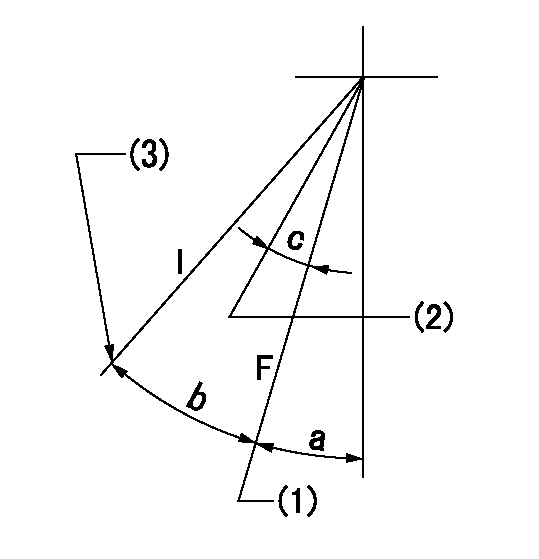
F:Full speed
I:Idle
(1)Set the pump speed at aa. ( At delivery )
(2)Set the pump speed at bb.
(3)Stopper bolt setting
----------
aa=900r/min bb=750r/min
----------
a=20deg+-5deg b=28deg+-5deg c=7deg+-5deg
----------
aa=900r/min bb=750r/min
----------
a=20deg+-5deg b=28deg+-5deg c=7deg+-5deg
Information:
(1) Bore in bearing of idler gear ... 28.600 0.048 mm (1.1260 .0019 in.) Diameter of shaft for the idler gear ... 28.512 0.013 mm (1.1225 .0005 in.)Clearance between bearing and shaft ... 0.028 to 0.150 mm (.0011 to .0059 in.)(2) Clearance between gear and body of pump ... 0.05 to 0.66 mm (.002 to .026 in.)(3) Diameter of shafts for pump ... 22.217 0.005 mm (.8747 .0002 in.) Bore in bearings for shafts (2P1785) ... 22.258 0.008 mm (.8763 .0003 in.)Bore in bearings for shafts (4W2448) ... 22.286 0.051 mm (.8774 .0020 in.)Clearance between shafts and bearings (2P1785) ... 0.028 to 0.053 mm (.0011 to .0021 in.)Clearance between shafts and bearings (4W2448) ... 0.025 to 0.127 mm (.0010 to .0050 in.)(4) Depth that bearings are installed in pump bodies ... 1.5 0.25 mm (.060 .010 in.)(5) Gear. Length of gears ... 50.808 0.025 mm (2.0003 .0010 in.) Depth of bore in pump body for gears ... 50.935 0.020 mm (2.0053 .0008 in.)Clearance between end of gears and pump body ... 0.081 to 0.173 mm (.0032 to .0068 in.)(6) Length of gears ... 38.070 0.025 mm (1.4988 .0010 in.) Depth of bore in pump body for gears ... 38.197 0.020 mm (1.5038 .0008 in.)Clearance between end of gears and pump body ... 0.081 to 0.173 mm (.0032 to .0068 in.)(7) Distance from the end of the idler shafts to gear faces ... 21.03 .127 mm (.828 .005 in.) Maximum temperature of gear when shrinking in place ... 398°C (750°F)(8) Distance from the end of the drive shaft to gear face ... 38.2 0.12 mm (1.505 .005 in.) Maximum temperature of gear when shrinking in place ... 398°C (750°F)(9) Torque for bolt holding drive gear to drive shaft ... 43 7 N m (32 5 lb ft) Install the bearings in the cover and body for the oil pump so the bearing junctions (joints) are in the position shown.(10) Distance dowel extends from body ... 6.0 0.5 mm (.24 .02 in.)(11) Shaft assembly. Distance shaft assembly extends from body ... 30.50 0.25 mm (1.200 .010 in.) Before running, lubricate pump with oil. Pump must rotate freely by hand.
Have questions with 101602-9141?
Group cross 101602-9141 ZEXEL
Daewoo
Yanmar
101602-9141
9 400 610 632
12665051041
INJECTION-PUMP ASSEMBLY
6HAL
6HAL