Information injection-pump assembly
BOSCH
9 400 614 970
9400614970
ZEXEL
101602-9131
1016029131
YANMAR
12665051031
12665051031

Rating:
Service parts 101602-9131 INJECTION-PUMP ASSEMBLY:
1.
_
5.
AUTOM. ADVANCE MECHANIS
6.
COUPLING PLATE
7.
COUPLING PLATE
8.
_
9.
_
10.
NOZZLE AND HOLDER ASSY
11.
Nozzle and Holder
12.
Open Pre:MPa(Kqf/cm2)
13.
NOZZLE-HOLDER
14.
NOZZLE
15.
NOZZLE SET
Cross reference number
BOSCH
9 400 614 970
9400614970
ZEXEL
101602-9131
1016029131
YANMAR
12665051031
12665051031
Zexel num
Bosch num
Firm num
Name
101602-9131
9 400 614 970
12665051031 YANMAR
INJECTION-PUMP ASSEMBLY
6HAL K 14BE INJECTION PUMP ASSY PE6A PE
6HAL K 14BE INJECTION PUMP ASSY PE6A PE
Calibration Data:
Adjustment conditions
Test oil
1404 Test oil ISO4113 or {SAEJ967d}
1404 Test oil ISO4113 or {SAEJ967d}
Test oil temperature
degC
40
40
45
Nozzle and nozzle holder
105780-8140
Bosch type code
EF8511/9A
Nozzle
105780-0000
Bosch type code
DN12SD12T
Nozzle holder
105780-2080
Bosch type code
EF8511/9
Opening pressure
MPa
17.2
Opening pressure
kgf/cm2
175
Injection pipe
Outer diameter - inner diameter - length (mm) mm 6-2-600
Outer diameter - inner diameter - length (mm) mm 6-2-600
Overflow valve opening pressure
kPa
157
123
191
Overflow valve opening pressure
kgf/cm2
1.6
1.25
1.95
Tester oil delivery pressure
kPa
157
157
157
Tester oil delivery pressure
kgf/cm2
1.6
1.6
1.6
Direction of rotation (viewed from drive side)
Right R
Right R
Injection timing adjustment
Direction of rotation (viewed from drive side)
Right R
Right R
Injection order
1-4-2-6-
3-5
Pre-stroke
mm
2.7
2.65
2.75
Beginning of injection position
Drive side NO.1
Drive side NO.1
Difference between angles 1
Cal 1-4 deg. 60 59.5 60.5
Cal 1-4 deg. 60 59.5 60.5
Difference between angles 2
Cyl.1-2 deg. 120 119.5 120.5
Cyl.1-2 deg. 120 119.5 120.5
Difference between angles 3
Cal 1-6 deg. 180 179.5 180.5
Cal 1-6 deg. 180 179.5 180.5
Difference between angles 4
Cal 1-3 deg. 240 239.5 240.5
Cal 1-3 deg. 240 239.5 240.5
Difference between angles 5
Cal 1-5 deg. 300 299.5 300.5
Cal 1-5 deg. 300 299.5 300.5
Injection quantity adjustment
Adjusting point
A
Rack position
12.7
Pump speed
r/min
900
900
900
Each cylinder's injection qty
mm3/st.
121
118.6
123.4
Basic
*
Fixing the rack
*
Injection quantity adjustment_02
Adjusting point
B
Rack position
7.5+-0.5
Pump speed
r/min
250
250
250
Each cylinder's injection qty
mm3/st.
15
13.5
16.5
Fixing the rack
*
Test data Ex:
Governor adjustment
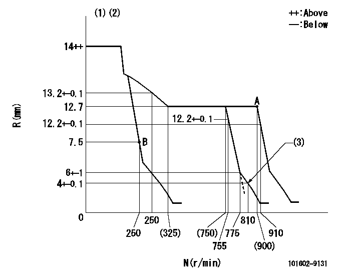
N:Pump speed
R:Rack position (mm)
(1)Target notch: K
(2)Tolerance for racks not indicated: +-0.05mm.
(3)Set idle sub-spring
----------
K=13
----------
----------
K=13
----------
Speed control lever angle
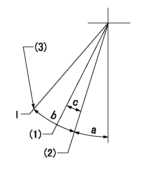
I:Idle
(1)When pump speed set at aa
(2)Set the pump speed at bb (at delivery)
(3)Stopper bolt setting
----------
aa=755r/min bb=910r/min
----------
a=20deg+-5deg b=28deg+-5deg c=7deg+-5deg
----------
aa=755r/min bb=910r/min
----------
a=20deg+-5deg b=28deg+-5deg c=7deg+-5deg
Stop lever angle
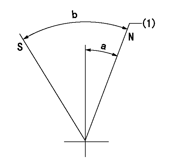
N:Pump normal
S:Stop the pump.
(1)Normal
----------
----------
a=20deg+-5deg b=53deg+-5deg
----------
----------
a=20deg+-5deg b=53deg+-5deg
Information:
(1) 7S7144 Spring for valves (new): Length under test force ... 44.86 mm (1.766 in.)Test force ... 257 25 N (57.7 4.5 lb.)Use again minimum load at length under test force ... 217 N (48.83 lb.)Length of spring at valve open position ... 32.28 mm (1.271 in.)Use again minimum load at valve open position ... 658 N (148.5 lb.)Free length after test ... 52.07 mm (2.05 in.)Outside diameter ... 35.21 mm (1.386 in.)Spring must not be bent more than ... 1.82 mm (.072 in.)(2) Height to top of valve guide ... 22.23 0.25 mm (.875 .010 in.)(3) Diameter of valve stem (new) ... 9.441 0.008 mm (.3717 .0003 in.) Use again minimum diameter ... 9.408 mm (.3704 in.)Bore in valve guide with guide installed in the head.Minimum permissible (new) ... 9.456 mm (.3723 in.)Maximum permissible (worn) ... 9.581 mm (.3772 in.)(4) Valve lip thickness: 6N9916 Exhaust ValveUse again minimum ... 2.69 mm (.106 in.)6N9915 Intake ValveUse again minimum ... 2.44 mm (.096 in.)(5) Diameter of valve head: Exhaust valve ... 48.16 0.13 mm (1.896 .005 in.)Intake valve ... 51.31 0.13 mm (2.020 .005 in.)(6) Angle of valve face ... 29 1/4 1/4° (7) Depth of bore in head for valve seat insert ... 12.28 0.13 mm (.483 .005 in.)(8) Diameter of valve seat insert for exhaust valve ... 50.889 0.013 mm (2.0035 .0005 in.) Bore in head for valve seat insert for exhaust valve ... 50.813 0.030 mm (2.0005 .0012 in.)Diameter of valve seat insert for intake valve ... 52.032 0.013 mm (2.0485 .0005 in.)Bore in head for valve seat insert for intake valve ... 51.956 0.030 mm (2.0455 .0012 in.)(9) Angle of face of valve seat insert ... 30 1°(10) Maximum permissible width of valve seat (intake and exhaust) ... 1.93 mm (.076 in.) Minimum permissible width of valve seat (intake and exhaust) ... 1.14 mm (.045 in.)(11) Dimension from top of closed valve to face of head: Minimum permissible dimension for 6N9916 Exhaust Valve ... 0.66 mm (.026 in.)Minimum permissible dimension for 6N9915 Intake Valve ... 0.15 mm (.006 in.)(12) Outside diameter of the face of the valve seat insert: Exhaust seat ... 46.02 mm (1.812 in.)Maximum permissible, exhaust seat ... 47.29 mm (1.862 in.)Intake seat ... 49.28 mm (1.940 in.)Maximum permissible, intake seat ... 50.55 mm (1.990 in.)(13) Angle to grind seat face of the insert to get a reduction of maximum seat diameter ... 15°Procedure to Check Intake Valve Timing
1. Check the No. 1 intake valve clearance with the engine stopped. The valve clearance must be 0.30 to 0.46 mm (.012 to .018 in.). If the valve clearance is not in this range, adjust the clearance to .038 mm (.015 in.).2. Mark Top Center Position of the crankshaft on the vibration damper or pulley.3. Use a dial indicator to measure the intake valve movement.4. Rotate the crankshaft in the direction of normal
1. Check the No. 1 intake valve clearance with the engine stopped. The valve clearance must be 0.30 to 0.46 mm (.012 to .018 in.). If the valve clearance is not in this range, adjust the clearance to .038 mm (.015 in.).2. Mark Top Center Position of the crankshaft on the vibration damper or pulley.3. Use a dial indicator to measure the intake valve movement.4. Rotate the crankshaft in the direction of normal
Have questions with 101602-9131?
Group cross 101602-9131 ZEXEL
Daewoo
Yanmar
101602-9131
9 400 614 970
12665051031
INJECTION-PUMP ASSEMBLY
6HAL
6HAL