Information injection-pump assembly
BOSCH
9 400 612 943
9400612943
ZEXEL
101602-8761
1016028761
ISUZU
1156033350
1156033350
Rating:
Service parts 101602-8761 INJECTION-PUMP ASSEMBLY:
1.
_

5.
AUTOM. ADVANCE MECHANIS
8.
_
9.
_
11.
Nozzle and Holder
1-15300-331-0
12.
Open Pre:MPa(Kqf/cm2)
18.1{185}

15.
NOZZLE SET
Include in #1:
101602-8761
as INJECTION-PUMP ASSEMBLY
Include in #2:
104741-6421
as _
Cross reference number
BOSCH
9 400 612 943
9400612943
ZEXEL
101602-8761
1016028761
ISUZU
1156033350
1156033350
Zexel num
Bosch num
Firm num
Name
101602-8761
9 400 612 943
1156033350 ISUZU
INJECTION-PUMP ASSEMBLY
6BG1-T K 14BF INJECTION PUMP ASSY PE6AD PE
6BG1-T K 14BF INJECTION PUMP ASSY PE6AD PE
Calibration Data:
Adjustment conditions
Test oil
1404 Test oil ISO4113 or {SAEJ967d}
1404 Test oil ISO4113 or {SAEJ967d}
Test oil temperature
degC
40
40
45
Nozzle and nozzle holder
105780-8140
Bosch type code
EF8511/9A
Nozzle
105780-0000
Bosch type code
DN12SD12T
Nozzle holder
105780-2080
Bosch type code
EF8511/9
Opening pressure
MPa
17.2
Opening pressure
kgf/cm2
175
Injection pipe
Outer diameter - inner diameter - length (mm) mm 6-2-600
Outer diameter - inner diameter - length (mm) mm 6-2-600
Overflow valve
131424-4920
Overflow valve opening pressure
kPa
127
107
147
Overflow valve opening pressure
kgf/cm2
1.3
1.1
1.5
Tester oil delivery pressure
kPa
157
157
157
Tester oil delivery pressure
kgf/cm2
1.6
1.6
1.6
Direction of rotation (viewed from drive side)
Right R
Right R
Injection timing adjustment
Direction of rotation (viewed from drive side)
Right R
Right R
Injection order
1-5-3-6-
2-4
Pre-stroke
mm
3.6
3.55
3.65
Beginning of injection position
Drive side NO.1
Drive side NO.1
Difference between angles 1
Cal 1-5 deg. 60 59.5 60.5
Cal 1-5 deg. 60 59.5 60.5
Difference between angles 2
Cal 1-3 deg. 120 119.5 120.5
Cal 1-3 deg. 120 119.5 120.5
Difference between angles 3
Cal 1-6 deg. 180 179.5 180.5
Cal 1-6 deg. 180 179.5 180.5
Difference between angles 4
Cyl.1-2 deg. 240 239.5 240.5
Cyl.1-2 deg. 240 239.5 240.5
Difference between angles 5
Cal 1-4 deg. 300 299.5 300.5
Cal 1-4 deg. 300 299.5 300.5
Injection quantity adjustment
Adjusting point
A
Rack position
10.5
Pump speed
r/min
1075
1075
1075
Average injection quantity
mm3/st.
93
91.5
94.5
Max. variation between cylinders
%
0
-2
2
Basic
*
Fixing the lever
*
Injection quantity adjustment_02
Adjusting point
C
Rack position
7.4+-0.5
Pump speed
r/min
450
450
450
Average injection quantity
mm3/st.
9.5
8.2
10.8
Max. variation between cylinders
%
0
-14
14
Fixing the rack
*
Injection quantity adjustment_03
Adjusting point
D
Rack position
-
Pump speed
r/min
100
100
100
Average injection quantity
mm3/st.
95
90
100
Fixing the lever
*
Rack limit
*
Test data Ex:
Governor adjustment
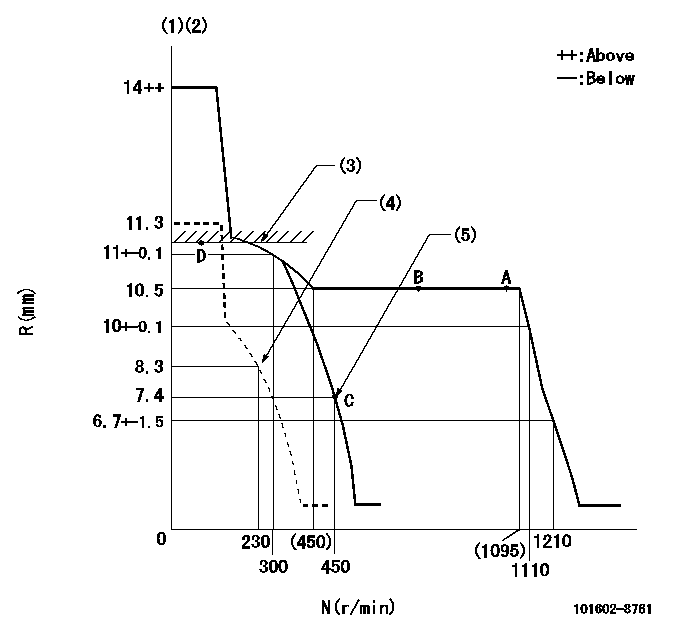
N:Pump speed
R:Rack position (mm)
(1)Notch fixed: K
(2)Tolerance for racks not indicated: +-0.05mm.
(3)RACK LIMIT
(4)Set idle sub-spring
(5)Main spring setting
----------
K=10
----------
----------
K=10
----------
Speed control lever angle
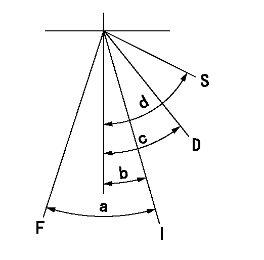
F:Full speed
I:Idle
S:Stop
D:Dead point
----------
----------
a=(20deg)+-5deg b=(18deg)+-5deg c=20deg+-3deg d=(35deg)+-5deg
----------
----------
a=(20deg)+-5deg b=(18deg)+-5deg c=20deg+-3deg d=(35deg)+-5deg
Stop lever angle

N:Pump normal
S:Stop the pump.
(1)Normal
----------
----------
a=13deg+-5deg b=53deg+-5deg
----------
----------
a=13deg+-5deg b=53deg+-5deg
0000001501 LEVER
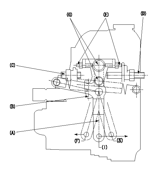
1. Variable lever adjustment
(1)Fix lever B in the idle position using the bolts C and D.
(2)Temporarily fix lever A in center of long hole.
(3)Set the dead point position temporarily and measure the lever angle.
(4)After idle adjustment, loosen the full side stopper bolt D.
(5)Move lever A in full speed direction.
(6)Fix the bolt D at the full speed position.
(7)Fix lever A using bolt E.
(8)(G) Lock using bolt.
(9)Finally, measure the lever angle and set the idle stopper bolt (C) stop position.
----------
----------
----------
----------
Timing setting

(1)Pump vertical direction
(2)Position of coupling's threaded hole at No 1 cylinder's beginning of injection
(3)B.T.D.C.: aa
(4)-
----------
aa=12deg
----------
a=(60deg)
----------
aa=12deg
----------
a=(60deg)
Information:
REM07-31
Reman
October 2007PRODUCT LINE ADDITION: REMANUFACTURED FUEL INJECTORS FOR VARIOUS INDUSTRIAL, MACHINE, AND MARINE ENGINE APPLICATIONS AnnouncementThe Caterpillar Remanufactured Products Group announces the expansion of the remanufactured injector product line to include coverage for various C7, C9, and 3306 industrial, machine, and marine applications. CoverageThe introduction of these injectors provides dealers with an additional, lower cost repair option for various C7, C9, and 3306 engine applications. Refer to the tables below for model usage. Features and BenefitsCat? Remanufactured injectors offer excellent value to customers. Customers who want fast repair turn-around, superior quality and reliability, and lower repair costs will benefit from the use of these Remanufactured injectors by providing immediate, off-the-shelf availability at a fraction of the new price. Core Acceptance Core Acceptance Crietira for Catperillar Remanufactured injectors is simple. Full core credit is issued when the core is fully assembled, there is no excessive rust or non-operational damage and it is an acceptable part number. Consult your Core Acceptance Guide for complete details.WarrantyPlease consult the appropriate warranty statement for your area.
PELJ0827 CATERPILLAR? ?2007 Caterpillar
Have questions with 101602-8761?
Group cross 101602-8761 ZEXEL
Isuzu
Isuzu
Isuzu
Isuzu
101602-8761
9 400 612 943
1156033350
INJECTION-PUMP ASSEMBLY
6BG1-T
6BG1-T