Information injection-pump assembly
BOSCH
9 400 610 621
9400610621
ZEXEL
101602-8340
1016028340
ISUZU
1156031590
1156031590

Rating:
Service parts 101602-8340 INJECTION-PUMP ASSEMBLY:
1.
_
5.
AUTOM. ADVANCE MECHANIS
8.
_
9.
_
11.
Nozzle and Holder
1-15300-291-2
12.
Open Pre:MPa(Kqf/cm2)
18.1{185}
15.
NOZZLE SET
Include in #1:
101602-8340
as INJECTION-PUMP ASSEMBLY
Include in #2:
104741-6130
as _
Cross reference number
BOSCH
9 400 610 621
9400610621
ZEXEL
101602-8340
1016028340
ISUZU
1156031590
1156031590
Zexel num
Bosch num
Firm num
Name
101602-8340
9 400 610 621
1156031590 ISUZU
INJECTION-PUMP ASSEMBLY
6BG1 K 14BE INJECTION PUMP ASSY PE6A PE
6BG1 K 14BE INJECTION PUMP ASSY PE6A PE
Calibration Data:
Adjustment conditions
Test oil
1404 Test oil ISO4113 or {SAEJ967d}
1404 Test oil ISO4113 or {SAEJ967d}
Test oil temperature
degC
40
40
45
Nozzle and nozzle holder
105780-8140
Bosch type code
EF8511/9A
Nozzle
105780-0000
Bosch type code
DN12SD12T
Nozzle holder
105780-2080
Bosch type code
EF8511/9
Opening pressure
MPa
17.2
Opening pressure
kgf/cm2
175
Injection pipe
Outer diameter - inner diameter - length (mm) mm 6-2-600
Outer diameter - inner diameter - length (mm) mm 6-2-600
Overflow valve
131424-4920
Overflow valve opening pressure
kPa
127
107
147
Overflow valve opening pressure
kgf/cm2
1.3
1.1
1.5
Tester oil delivery pressure
kPa
157
157
157
Tester oil delivery pressure
kgf/cm2
1.6
1.6
1.6
Direction of rotation (viewed from drive side)
Right R
Right R
Injection timing adjustment
Direction of rotation (viewed from drive side)
Right R
Right R
Injection order
1-5-3-6-
2-4
Pre-stroke
mm
3.6
3.55
3.65
Beginning of injection position
Drive side NO.1
Drive side NO.1
Difference between angles 1
Cal 1-5 deg. 60 59.5 60.5
Cal 1-5 deg. 60 59.5 60.5
Difference between angles 2
Cal 1-3 deg. 120 119.5 120.5
Cal 1-3 deg. 120 119.5 120.5
Difference between angles 3
Cal 1-6 deg. 180 179.5 180.5
Cal 1-6 deg. 180 179.5 180.5
Difference between angles 4
Cyl.1-2 deg. 240 239.5 240.5
Cyl.1-2 deg. 240 239.5 240.5
Difference between angles 5
Cal 1-4 deg. 300 299.5 300.5
Cal 1-4 deg. 300 299.5 300.5
Injection quantity adjustment
Adjusting point
A
Rack position
8.8
Pump speed
r/min
800
800
800
Average injection quantity
mm3/st.
59.5
58
61
Max. variation between cylinders
%
0
-2
2
Basic
*
Fixing the lever
*
Injection quantity adjustment_02
Adjusting point
-
Rack position
7+-0.5
Pump speed
r/min
375
375
375
Average injection quantity
mm3/st.
8
6.7
9.3
Max. variation between cylinders
%
0
-14
14
Fixing the rack
*
Remarks
Adjust only variation between cylinders; adjust governor according to governor specifications.
Adjust only variation between cylinders; adjust governor according to governor specifications.
Injection quantity adjustment_03
Adjusting point
D
Rack position
-
Pump speed
r/min
100
100
100
Average injection quantity
mm3/st.
105
100
110
Fixing the lever
*
Rack limit
*
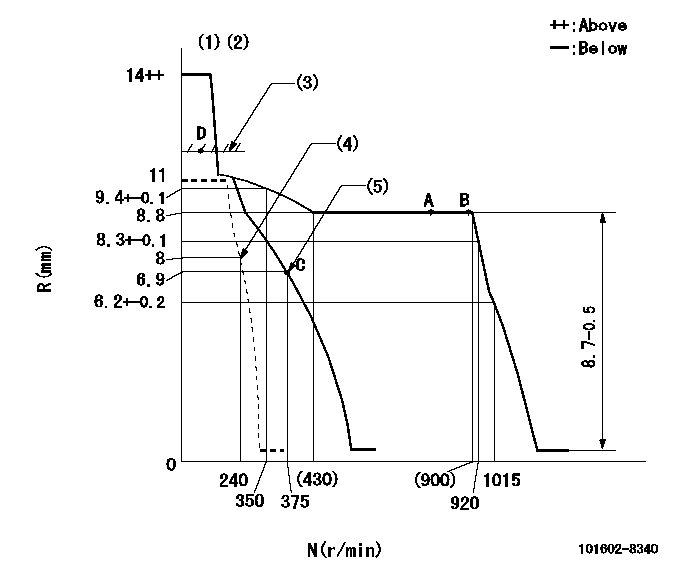
Test data Ex:
Governor adjustment

N:Pump speed
R:Rack position (mm)
(1)Target notch: K
(2)Tolerance for racks not indicated: +-0.05mm.
(3)RACK LIMIT
(4)Set idle sub-spring
(5)Main spring setting
----------
K=8
----------
----------
K=8
----------
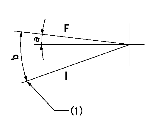
Speed control lever angle

F:Full speed
I:Idle
(1)Stopper bolt setting
----------
----------
a=1deg+-5deg b=13deg+-5deg
----------
----------
a=1deg+-5deg b=13deg+-5deg
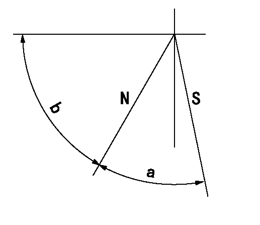
Stop lever angle

N:Pump normal
S:Stop the pump.
----------
----------
a=46deg+-5deg b=52deg+-5deg
----------
----------
a=46deg+-5deg b=52deg+-5deg
Timing setting

(1)Pump vertical direction
(2)Position of flywheel's threaded hole at No 1 cylinder's beginning of injection
(3)B.T.D.C.: aa
(4)-
----------
aa=14deg
----------
a=(10deg)
----------
aa=14deg
----------
a=(10deg)
Information:
Machine Specs.
Is stallcondition repeatable Can dealer reproduce?
WaterSeparator / Filter Does the Water Separator / Filter have water in it andwhat is the amount?
Is thegovernor assembly free to operate? Inspect pedal and cables for properoperation and no signs of significant wear or binding
Lowidle speed (no load) rpm
Highidle speed (no load) rpm
Torqueconverter stall speed (engine rpm) Record engine rpm as per RENR3574 Test& Adjust, Transmission and Torque converter testDirect Drive Transmission Arrangement
HP Rating Stall RPM 75 hp 1975 75 RPM 80 hp 2050 75 RPM 85 hp 2075 75 RPM 93 hp 2160 75 RPM Auto shift Transmission Arrangement
HP Rating Stall RPM 75 hp 2068 75 RPM 81 hp 2164 75RPM 90 hp 2206 75 RPM 98 hp 2218 75 RPM Note: Stall speeds are calculated usingNo. 2 diesel fuel.
Turboboost pressure at torque converter stall(full load boost spec is 82 - 85 kPa)
CoolantTemperature (at torque converter stall based on gage reading)
Smokecolor during torque converter stall test (if any) Is the smoke Black, Blue,White or none visible
HydraulicPump Test and Adjust RENR3584 Check for correct system pressure and torquelimiter settings. (Note: this step may be skipped if the dealer can confirmthat the hydraulic system has not been tampered with ? factory settingsare intact.)
Test235-1790 switch for proper operation. Cold advance for FIP, switch openscircuit when the coolant temp reaches 37-43 deg. C and closes at 27-33deg C.
"Wiggle"check electrical connections to and from FIP shutoff solenoid, cold startadvance, and electric lift pump circuit.
Machine Condition
Restrictionsin induction system present Check condition of Air filter and for debrisin the air pre-cleaner.
Restrictionsin exhaust system present?
Blockedfuel tank vent (fuel filler cap)
FuelSystem
SpecificChecks/Tests required Response
Fueltank temperature during either stall condition.
Checkfuel connections, fittings and clips. Check for looseness or fuel leakage.
Lowpressure fuel line interference conditions / restrictions (I.e. check routingof low pressure fuel line). Reference Service Magazine article on low pressurefuel system checks dated 23 Jun 2003.
Aeration(air present in fuel) See RENR2415 Test & Adjust. Air in Fuel ? Test(See illustration 1 for proper installation of clear tube on fuel injectionpump return line).
Fuelflow (low pressure fuel system) See RENR2415 Test & Adjust. Fuel SystemPressure- Test
Doesthe engine perform OK from a separate feed to the FIP? (Suspending a cleancontainer of clean fuel to gravity feed the FIP or fixing a slave liftpump directly to the FIP would eliminate the low pressure circuit on themachine)
Whatwas done to overcome the problem? Illustration 1
Have questions with 101602-8340?
Group cross 101602-8340 ZEXEL
Isuzu
Isuzu
101602-8340
9 400 610 621
1156031590
INJECTION-PUMP ASSEMBLY
6BG1
6BG1
