Information injection-pump assembly
BOSCH
9 400 610 619
9400610619
ZEXEL
101602-8320
1016028320
ISUZU
1156031570
1156031570

Rating:
Service parts 101602-8320 INJECTION-PUMP ASSEMBLY:
1.
_
5.
AUTOM. ADVANCE MECHANIS
6.
COUPLING PLATE
8.
_
9.
_
11.
Nozzle and Holder
1-15300-291-2
12.
Open Pre:MPa(Kqf/cm2)
18.1{185}
15.
NOZZLE SET
Cross reference number
BOSCH
9 400 610 619
9400610619
ZEXEL
101602-8320
1016028320
ISUZU
1156031570
1156031570
Zexel num
Bosch num
Firm num
Name
101602-8320
9 400 610 619
1156031570 ISUZU
INJECTION-PUMP ASSEMBLY
6BG1 K 14BE INJECTION PUMP ASSY PE6A PE
6BG1 K 14BE INJECTION PUMP ASSY PE6A PE
Calibration Data:
Adjustment conditions
Test oil
1404 Test oil ISO4113 or {SAEJ967d}
1404 Test oil ISO4113 or {SAEJ967d}
Test oil temperature
degC
40
40
45
Nozzle and nozzle holder
105780-8140
Bosch type code
EF8511/9A
Nozzle
105780-0000
Bosch type code
DN12SD12T
Nozzle holder
105780-2080
Bosch type code
EF8511/9
Opening pressure
MPa
17.2
Opening pressure
kgf/cm2
175
Injection pipe
Outer diameter - inner diameter - length (mm) mm 6-2-600
Outer diameter - inner diameter - length (mm) mm 6-2-600
Overflow valve
131424-4920
Overflow valve opening pressure
kPa
127
107
147
Overflow valve opening pressure
kgf/cm2
1.3
1.1
1.5
Tester oil delivery pressure
kPa
157
157
157
Tester oil delivery pressure
kgf/cm2
1.6
1.6
1.6
Direction of rotation (viewed from drive side)
Right R
Right R
Injection timing adjustment
Direction of rotation (viewed from drive side)
Right R
Right R
Injection order
1-5-3-6-
2-4
Pre-stroke
mm
3.6
3.55
3.65
Beginning of injection position
Drive side NO.1
Drive side NO.1
Difference between angles 1
Cal 1-5 deg. 60 59.5 60.5
Cal 1-5 deg. 60 59.5 60.5
Difference between angles 2
Cal 1-3 deg. 120 119.5 120.5
Cal 1-3 deg. 120 119.5 120.5
Difference between angles 3
Cal 1-6 deg. 180 179.5 180.5
Cal 1-6 deg. 180 179.5 180.5
Difference between angles 4
Cyl.1-2 deg. 240 239.5 240.5
Cyl.1-2 deg. 240 239.5 240.5
Difference between angles 5
Cal 1-4 deg. 300 299.5 300.5
Cal 1-4 deg. 300 299.5 300.5
Injection quantity adjustment
Adjusting point
A
Rack position
9.1
Pump speed
r/min
1200
1200
1200
Average injection quantity
mm3/st.
64
62.5
65.5
Max. variation between cylinders
%
0
-2
2
Basic
*
Fixing the lever
*
Injection quantity adjustment_02
Adjusting point
-
Rack position
7.1+-0.5
Pump speed
r/min
350
350
350
Average injection quantity
mm3/st.
8
6.7
9.3
Max. variation between cylinders
%
0
-14
14
Fixing the rack
*
Remarks
Adjust only variation between cylinders; adjust governor according to governor specifications.
Adjust only variation between cylinders; adjust governor according to governor specifications.
Injection quantity adjustment_03
Adjusting point
D
Rack position
-
Pump speed
r/min
100
100
100
Average injection quantity
mm3/st.
95
90
100
Fixing the lever
*
Rack limit
*
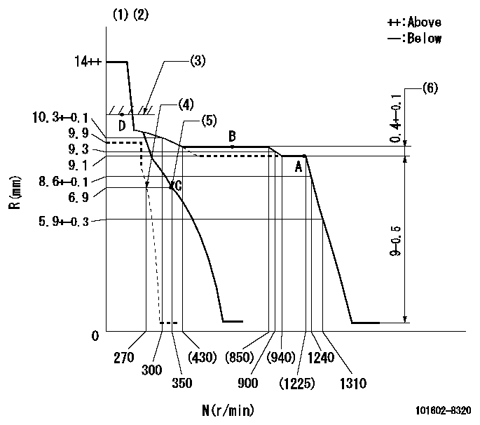
Test data Ex:
Governor adjustment

N:Pump speed
R:Rack position (mm)
(1)Target notch: K
(2)Tolerance for racks not indicated: +-0.05mm.
(3)RACK LIMIT
(4)Set idle sub-spring
(5)Main spring setting
(6)Rack difference between N = N1 and N = N2
----------
K=15 N1=1200r/min N2=700r/min
----------
----------
K=15 N1=1200r/min N2=700r/min
----------
Speed control lever angle

F:Full speed
I:Idle
(1)Stopper bolt setting
----------
----------
a=10deg+-5deg b=23deg+-5deg
----------
----------
a=10deg+-5deg b=23deg+-5deg
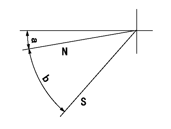
Stop lever angle

N:Pump normal
S:Stop the pump.
----------
----------
a=2.5deg+-5deg b=46deg+-5deg
----------
----------
a=2.5deg+-5deg b=46deg+-5deg
Timing setting

(1)Pump vertical direction
(2)Position of gear mark 'CC' at No 1 cylinder's beginning of injection
(3)B.T.D.C.: aa
(4)-
----------
aa=14deg
----------
a=(95deg)
----------
aa=14deg
----------
a=(95deg)
Information:
This Program can only be administeredafter a failure occurs. The decision whether to apply the Program is madeby the dealer. When reporting the repair, use "PS50780" as the Part numberand "7755" as the Group Number. Use "96" as the Warranty Claim DescriptionCode and use "Z" as the SIMS Description Code. The information supplied in this serviceletter may not be valid after the termination date of this program. Donot perform the work outlined in this Service Letter after the terminationdate without first contacting your Caterpillar product analyst. This Revised Service Letter replacesthe April 2, 2004 (Revised April 2004) Service Letter. Changes have beenmade to the Affected Product.TERMINATION DATE
April 30, 2006PROBLEM
Failed injector and wiring harness need to bereplaced on certain C-9 Industrial Engines. The C-9 engine can developan injector misfire due to an open connection at the injector to harnessconnector. This misfire can be diagnosed with standard troubleshootingguide procedures.AFFECTED PRODUCT
Model Identification Number
C9 CLJ1-4259
12H 12500001-40AMZ1-496CBK1-353
330C B1K1-178B2L1-203B4N1-187BTM1-189CGZ1-511CYA1-287D3C1-231JAB1-626JCD1-292JNK1-245KDD1-580MCA1-427MKM1-308GAG1-329RBH1-233
330C L CAP1-1257DKY1-2011HAA1-393
D6R II AEM1-100AFM1-115BLE1-199BLT1-186BMK1-121BNL1-99BPM1-101BPP1-97BPS1-102BRJ1-116
D6R II LGP ACJ1-101ADE1-311BNC1-265BPZ1-142
D6R II XL AAX1-465BMJ1-130BMY1-297BRZ1-115CAD1-143FDT1-141
D6R II XW AEP1-223DAE1-129
470 7651-811
475 7671-824
MT765 AMS1-266
TK711 10100001-00191
TK721 10200001-00191
TK722 10300001-00193
TK732 10400185-00190
627G CEX187-296
637G CEH222-255PARTS NEEDED
Qty
Part Number
Description
1 1567106 Wiring Kit
1 1889865 Harness Assembly
1 2359651 Bolt - Socket
1 2360962 Injector GroupACTION REQUIRED
Replace the single failed injector with the new 2360962 Injector and the1889865 Wiring Harness Assembly. Refer to REHS1809 Special Instructionfor use of the 1567106 Wiring Kit.SERVICE CLAIM ALLOWANCES
Product smu/age whichever comes first Caterpillar Dealer Suggested Customer Suggested
Parts Labor Hrs Parts Labor Hrs Parts Labor Hrs
0-5000
0-35 months 100% 2.0 0 0 0 0
This is a 2?hour job.PARTS DISPOSITION
Handle the parts in accordance with your Warranty Bulletin on warrantyparts handling.
Have questions with 101602-8320?
Group cross 101602-8320 ZEXEL
Isuzu
Isuzu
101602-8320
9 400 610 619
1156031570
INJECTION-PUMP ASSEMBLY
6BG1
6BG1
