Information injection-pump assembly
BOSCH
9 400 611 695
9400611695
ZEXEL
101602-7660
1016027660
ISUZU
1156028100
1156028100
Rating:
Service parts 101602-7660 INJECTION-PUMP ASSEMBLY:
1.
_
5.
AUTOM. ADVANCE MECHANIS
6.
COUPLING PLATE
8.
_
9.
_
11.
Nozzle and Holder
1-15300-104-2
12.
Open Pre:MPa(Kqf/cm2)
18.1{185}

15.
NOZZLE SET
Include in #1:
101602-7660
as INJECTION-PUMP ASSEMBLY
Include in #2:
104740-1651
as _
Cross reference number
BOSCH
9 400 611 695
9400611695
ZEXEL
101602-7660
1016027660
ISUZU
1156028100
1156028100
Zexel num
Bosch num
Firm num
Name
101602-7660
9 400 611 695
1156028100 ISUZU
INJECTION-PUMP ASSEMBLY
6BD1-T K 14BE INJECTION PUMP ASSY PE6A PE
6BD1-T K 14BE INJECTION PUMP ASSY PE6A PE
Calibration Data:
Adjustment conditions
Test oil
1404 Test oil ISO4113 or {SAEJ967d}
1404 Test oil ISO4113 or {SAEJ967d}
Test oil temperature
degC
40
40
45
Nozzle and nozzle holder
105780-8140
Bosch type code
EF8511/9A
Nozzle
105780-0000
Bosch type code
DN12SD12T
Nozzle holder
105780-2080
Bosch type code
EF8511/9
Opening pressure
MPa
17.2
Opening pressure
kgf/cm2
175
Injection pipe
Outer diameter - inner diameter - length (mm) mm 6-2-600
Outer diameter - inner diameter - length (mm) mm 6-2-600
Overflow valve
132424-0620
Overflow valve opening pressure
kPa
157
123
191
Overflow valve opening pressure
kgf/cm2
1.6
1.25
1.95
Tester oil delivery pressure
kPa
157
157
157
Tester oil delivery pressure
kgf/cm2
1.6
1.6
1.6
RED3 control unit part number
407910-2
470
RED3 rack sensor specifications
mm
15
Direction of rotation (viewed from drive side)
Right R
Right R
Injection timing adjustment
Direction of rotation (viewed from drive side)
Right R
Right R
Injection order
1-5-3-6-
2-4
Pre-stroke
mm
3.2
3.15
3.25
Beginning of injection position
Drive side NO.1
Drive side NO.1
Difference between angles 1
Cal 1-5 deg. 60 59.5 60.5
Cal 1-5 deg. 60 59.5 60.5
Difference between angles 2
Cal 1-3 deg. 120 119.5 120.5
Cal 1-3 deg. 120 119.5 120.5
Difference between angles 3
Cal 1-6 deg. 180 179.5 180.5
Cal 1-6 deg. 180 179.5 180.5
Difference between angles 4
Cyl.1-2 deg. 240 239.5 240.5
Cyl.1-2 deg. 240 239.5 240.5
Difference between angles 5
Cal 1-4 deg. 300 299.5 300.5
Cal 1-4 deg. 300 299.5 300.5
Injection quantity adjustment
Rack position
(7.6)
Vist
V
2.48
2.48
2.48
Pump speed
r/min
900
900
900
Average injection quantity
mm3/st.
58
56.5
59.5
Max. variation between cylinders
%
0
-2.5
2.5
Basic
*
Injection quantity adjustment_02
Rack position
(5.9)
Vist
V
2.8
2.7
2.9
Pump speed
r/min
325
325
325
Average injection quantity
mm3/st.
10
8.7
11.3
Max. variation between cylinders
%
0
-14
14
Test data Ex:
Speed control lever angle
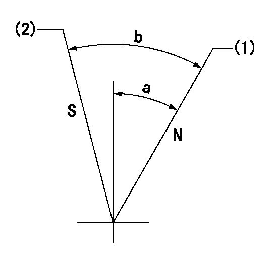
N:Pump normal
S:Stop the pump.
(1)Rack position = aa
(2)Rack position bb
----------
aa=16mm bb=1mm
----------
a=19deg+-5deg b=29deg+-5deg
----------
aa=16mm bb=1mm
----------
a=19deg+-5deg b=29deg+-5deg
0000000901

(1)Pump vertical direction
(2)Position of gear mark 'CC' at No 1 cylinder's beginning of injection
(3)B.T.D.C.: aa
(4)-
----------
aa=16deg
----------
a=(90deg)
----------
aa=16deg
----------
a=(90deg)
Stop lever angle

(Rs) rack sensor specifications
(C/U) control unit part number
(V) Rack sensor output voltage
(R) Rack position (mm)
1. Confirming governor output characteristics (rack 15 mm, span 6 mm)
(1)When the output voltages of the rack sensor are V1 and V2, check that the rack positions R1 and R2 in the table above are satisfied.
----------
----------
----------
----------
Information:
AFFECTED PRODUCT
Model Identification Number
993K Z4D00179-00182
PARTS NEEDED
Qty
Part Number Description
2 1R1808 FILTER-LUBE
12 8S9191 BOLT
4 3460335 CLAMP-BAND
12 3594060 INJECTOR GP-FUEL
1 BULK_OIL DEO-ULS (120 Liters)
In order to allow equitable parts availability to all participating dealers, please limit your initial parts order to not exceed 2% of dealership population. This is an initial order recommendation only, and the ultimate responsibility for ordering the total number of parts needed to satisfy the program lies with the dealer.
ACTION REQUIRED
If excessive fuel dilution of engine oil is found reference the following to determine the cause of fuel dilution.
Special Instruction, REHS3007,"Determining the Cause of Fuel Dilution of Engine Oil"
Troubleshooting, KENR9795, "C27 and C32 Engines for Caterpillar Built Machines"
Once an injector(s) has been identified as having a cracked/leaking injector body, replace the failed injector(s). Inspect the remaining good injector serial numbers with Cat ET, (Injector Serial Numbers = Injector trim file name, (ie 6Cxxxxxxxxxx.trm)). If the remaining injector serial numbers fall within the serial number range below, replace at the same time. Refer to Image 1 for the serial number location on the top of the electronic unit injector.
Injector Serial Numbers
6C001793971D through 6C002198297C
If an injector failure occurs on either of the rear two cylinders (right and/or left hand bank) the exhaust piping going from the turbo to the CEM will have to be removed. 346-0335 Exhaust Clamp cannot be reused and MUST be replaced with a new clamp. Refer to REHS5014, "Reuse Guideline for the Flexible Exhaust Pipe Group on Tier 4 Engines" for the proper installation and removal procedure. Refer to Image 2 for clamp location.
The 8S-9191 Injector Hold Down Bolts must be replaced.
Refer to Disassembly and Assembly, RENR9217 for the removal, installation, and tightening procedures.
After the engine is reassembled, change the engine oil and filters.
Image1
Image2
SERVICE CLAIM ALLOWANCES
Product smu/age whichever comes first Caterpillar Dealer Suggested Customer Suggested
Parts % Labor Hrs% Parts % Labor Hrs% Parts % Labor Hrs%
0-3500 hrs,
0-24 mo 100.0% 100.0% 0.0% 0.0% 0.0% 0.0%
3501-6000 hrs,
25-48 mo 33.0% 50.0% 0.0% 0.0% 50.0% 50.0%
This is a 10.0-hour job
If there has been a previous repair, part age/hours will apply. Retain a copy of the previous repair invoice in the dealer's records for audit purposes, and specify repair date and machine hours in the "Additional Comments" section of the warranty claim.
PARTS DISPOSITION
Handle the parts in accordance with your Warranty Bulletin on warranty parts handling.
Have questions with 101602-7660?
Group cross 101602-7660 ZEXEL
Isuzu
101602-7660
9 400 611 695
1156028100
INJECTION-PUMP ASSEMBLY
6BD1-T
6BD1-T