Information injection-pump assembly
BOSCH
9 400 614 909
9400614909
ZEXEL
101602-7632
1016027632
ISUZU
1156028702
1156028702
Rating:
Service parts 101602-7632 INJECTION-PUMP ASSEMBLY:
1.
_

5.
AUTOM. ADVANCE MECHANIS
6.
COUPLING PLATE
8.
_
9.
_
11.
Nozzle and Holder
5-15300-103-2
12.
Open Pre:MPa(Kqf/cm2)
14.7{150}

15.
NOZZLE SET
Cross reference number
BOSCH
9 400 614 909
9400614909
ZEXEL
101602-7632
1016027632
ISUZU
1156028702
1156028702
Zexel num
Bosch num
Firm num
Name
101602-7632
9 400 614 909
1156028702 ISUZU
INJECTION-PUMP ASSEMBLY
6BG1 K 14BE INJECTION PUMP ASSY PE6A PE
6BG1 K 14BE INJECTION PUMP ASSY PE6A PE
Calibration Data:
Adjustment conditions
Test oil
1404 Test oil ISO4113 or {SAEJ967d}
1404 Test oil ISO4113 or {SAEJ967d}
Test oil temperature
degC
40
40
45
Nozzle and nozzle holder
105780-8140
Bosch type code
EF8511/9A
Nozzle
105780-0000
Bosch type code
DN12SD12T
Nozzle holder
105780-2080
Bosch type code
EF8511/9
Opening pressure
MPa
17.2
Opening pressure
kgf/cm2
175
Injection pipe
Outer diameter - inner diameter - length (mm) mm 6-2-600
Outer diameter - inner diameter - length (mm) mm 6-2-600
Overflow valve
131424-4920
Overflow valve opening pressure
kPa
127
107
147
Overflow valve opening pressure
kgf/cm2
1.3
1.1
1.5
Tester oil delivery pressure
kPa
157
157
157
Tester oil delivery pressure
kgf/cm2
1.6
1.6
1.6
Direction of rotation (viewed from drive side)
Right R
Right R
Injection timing adjustment
Direction of rotation (viewed from drive side)
Right R
Right R
Injection order
1-5-3-6-
2-4
Pre-stroke
mm
3.6
3.55
3.65
Beginning of injection position
Drive side NO.1
Drive side NO.1
Difference between angles 1
Cal 1-5 deg. 60 59.5 60.5
Cal 1-5 deg. 60 59.5 60.5
Difference between angles 2
Cal 1-3 deg. 120 119.5 120.5
Cal 1-3 deg. 120 119.5 120.5
Difference between angles 3
Cal 1-6 deg. 180 179.5 180.5
Cal 1-6 deg. 180 179.5 180.5
Difference between angles 4
Cyl.1-2 deg. 240 239.5 240.5
Cyl.1-2 deg. 240 239.5 240.5
Difference between angles 5
Cal 1-4 deg. 300 299.5 300.5
Cal 1-4 deg. 300 299.5 300.5
Injection quantity adjustment
Adjusting point
A
Rack position
7.8
Pump speed
r/min
900
900
900
Average injection quantity
mm3/st.
35.1
33.6
36.6
Max. variation between cylinders
%
0
-2
2
Basic
*
Fixing the rack
*
Injection quantity adjustment_02
Adjusting point
-
Rack position
7.4+-0.5
Pump speed
r/min
390
390
390
Average injection quantity
mm3/st.
9.4
8.1
10.7
Max. variation between cylinders
%
0
-14
14
Fixing the rack
*
Remarks
Adjust only variation between cylinders; adjust governor according to governor specifications.
Adjust only variation between cylinders; adjust governor according to governor specifications.
Test data Ex:
Governor adjustment
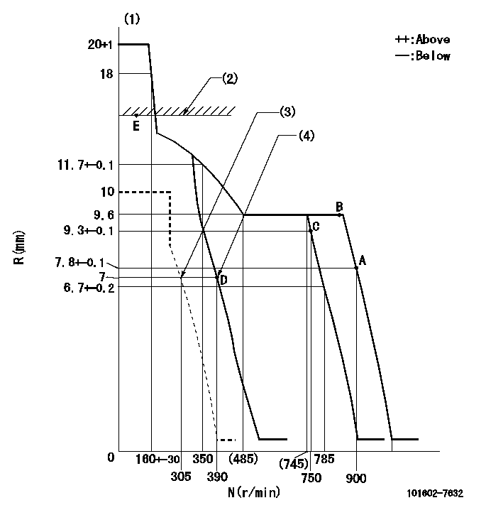
N:Pump speed
R:Rack position (mm)
(1)Target notch: K
(2)RACK LIMIT: RAL
(3)Set idle sub-spring
(4)Main spring setting
----------
K=8 RAL=13+-0.2mm
----------
----------
K=8 RAL=13+-0.2mm
----------
Speed control lever angle
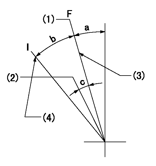
F:Full speed
I:Idle
(1)Set the pump speed at aa
(2)Set the pump speed at bb.
(3)Stopper bolt setting
(4)Stopper bolt setting
----------
aa=900r/min bb=750r/min
----------
a=2deg+-5deg b=18deg+-5deg c=4deg+-5deg
----------
aa=900r/min bb=750r/min
----------
a=2deg+-5deg b=18deg+-5deg c=4deg+-5deg
Stop lever angle
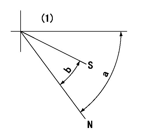
N:Pump normal
S:Stop the pump.
(1)No return spring
----------
----------
a=66.5deg+-5deg b=53deg+-5deg
----------
----------
a=66.5deg+-5deg b=53deg+-5deg
Timing setting

(1)Pump vertical direction
(2)Position of gear mark 'CC' at No 1 cylinder's beginning of injection
(3)B.T.D.C.: aa
(4)-
----------
aa=18deg
----------
a=(90deg)
----------
aa=18deg
----------
a=(90deg)
Information:
TERMINATION DATE
30Sep2014
PROBLEM
The existing fuel injectors can experience solenoid valve poppet seizures or poppet binding within injector body due to excessive thermal expansion. If the existing fuel injector fails it can result in complaints of misfire and/or low power.
AFFECTED PRODUCT
Model Identification Number
AD55B JNW00101-00151, 153-155, 157-166, 168-199, 201-244, 246, 248-269, 272-275, 60250
PARTS NEEDED
Qty
Part Number Description
12 8S9191 BOLT
24 3565212 BOLT-12 POINT HD
12 3740751 INJECTOR GP-FUEL
In order to allow equitable parts availability to all participating dealers, please limit your initial parts order to not exceed 7% of dealership population. This is an initial order recommendation only, and the ultimate responsibility for ordering the total number of parts needed to satisfy the program lies with the dealer.
ACTION REQUIRED
A fuel injector is considered failed if the following troubleshooting Step 1 and Step 2 are completed and the problem is not resolved. Troubleshooting is not cover by this letter.
1. Ensure ECM software is current.
2. Perform the following procedures:
KENR5424 ? Troubleshooting
SENR9937 - Electronic Unit Injector ? Adjust
SENR9937 - Electronic Unit Injector - Test
3. Replace injector(s) as required.
If one or more injectors fail replace all injectors at the time of repair.
Refer to Disassembly and Assembly, RENR9217 for the removal and installation procedure of the unit injector.
8S-9191 Injector Hold Down Bolt must be replaced. Ensure that the proper torque is achieved, 55 +/- 10 Nm (41 +/- 7 lb ft).
356-5212 Rocker Arm Shaft Hold Down Bolts must be replaced. Ensure that proper torque procedure is adhered to.
1. Position rocker arm shaft assembly (4) , valve rocker arms (3) , and electronic unit injector rocker arms (1) as a unit with 124-2946 Lifting Bracket on the cylinder head.
Note: Apply clean engine oil to the underside of the bolt heads prior to installation.
2. Install bolts (2) and tighten to a torque of 55 +/- 5 Nm (41 +/- 4 lb ft). Tighten bolts (2) again to a torque of 55 +/- 5 Nm (41 +/- 4 lb ft). Turn bolts (2) for an additional 60 +/- 5 degrees. Tighten the bolts in the following sequence: 2, 3, 1, 4.
Image1
SERVICE CLAIM ALLOWANCES
Product smu/age whichever comes first Caterpillar Dealer Suggested Customer Suggested
Parts % Labor Hrs% Parts % Labor Hrs% Parts % Labor Hrs%
0-6000 hrs,
0-18 mo 100.0% 100.0% 0.0% 0.0% 0.0% 0.0%
This is a 16.0-hour job
If there has been a previous repair, part age/hours will apply. Retain a copy of the previous repair invoice in the dealer's records for audit purposes, and specify repair date and machine hours in the "Additional Comments" section of the warranty claim.
PARTS DISPOSITION
Handle the parts in accordance with your Warranty Bulletin on warranty parts handling.
Have questions with 101602-7632?
Group cross 101602-7632 ZEXEL
Isuzu
101602-7632
9 400 614 909
1156028702
INJECTION-PUMP ASSEMBLY
6BG1
6BG1