Information injection-pump assembly
ZEXEL
101602-7630
1016027630
ISUZU
1156028700
1156028700
Rating:
Cross reference number
ZEXEL
101602-7630
1016027630
ISUZU
1156028700
1156028700
Zexel num
Bosch num
Firm num
Name
Calibration Data:
Adjustment conditions
Test oil
1404 Test oil ISO4113 or {SAEJ967d}
1404 Test oil ISO4113 or {SAEJ967d}
Test oil temperature
degC
40
40
45
Nozzle and nozzle holder
105780-8140
Bosch type code
EF8511/9A
Nozzle
105780-0000
Bosch type code
DN12SD12T
Nozzle holder
105780-2080
Bosch type code
EF8511/9
Opening pressure
MPa
17.2
Opening pressure
kgf/cm2
175
Injection pipe
Outer diameter - inner diameter - length (mm) mm 6-2-600
Outer diameter - inner diameter - length (mm) mm 6-2-600
Overflow valve
131424-4920
Overflow valve opening pressure
kPa
127
107
147
Overflow valve opening pressure
kgf/cm2
1.3
1.1
1.5
Tester oil delivery pressure
kPa
157
157
157
Tester oil delivery pressure
kgf/cm2
1.6
1.6
1.6
Direction of rotation (viewed from drive side)
Right R
Right R
Injection timing adjustment
Direction of rotation (viewed from drive side)
Right R
Right R
Injection order
1-5-3-6-
2-4
Pre-stroke
mm
3.6
3.55
3.65
Beginning of injection position
Drive side NO.1
Drive side NO.1
Difference between angles 1
Cal 1-5 deg. 60 59.5 60.5
Cal 1-5 deg. 60 59.5 60.5
Difference between angles 2
Cal 1-3 deg. 120 119.5 120.5
Cal 1-3 deg. 120 119.5 120.5
Difference between angles 3
Cal 1-6 deg. 180 179.5 180.5
Cal 1-6 deg. 180 179.5 180.5
Difference between angles 4
Cyl.1-2 deg. 240 239.5 240.5
Cyl.1-2 deg. 240 239.5 240.5
Difference between angles 5
Cal 1-4 deg. 300 299.5 300.5
Cal 1-4 deg. 300 299.5 300.5
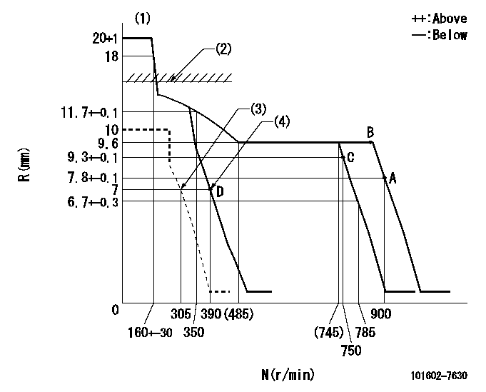
Injection quantity adjustment
Adjusting point
A
Rack position
7.8
Pump speed
r/min
900
900
900
Average injection quantity
mm3/st.
35.1
33.6
36.6
Max. variation between cylinders
%
0
-2
2
Basic
*
Fixing the rack
*
Injection quantity adjustment_02
Adjusting point
-
Rack position
7.4+-0.5
Pump speed
r/min
390
390
390
Average injection quantity
mm3/st.
9.4
8.1
10.7
Max. variation between cylinders
%
0
-14
14
Fixing the rack
*
Remarks
Adjust only variation between cylinders; adjust governor according to governor specifications.
Adjust only variation between cylinders; adjust governor according to governor specifications.
Test data Ex:
Governor adjustment
N:Pump speed
R:Rack position (mm)
(1)Target notch: K
(2)RACK CAP: R1
(3)Set idle sub-spring
(4)Main spring setting
----------
K=8 R1=(17.5)mm
----------
----------
K=8 R1=(17.5)mm
----------
Speed control lever angle
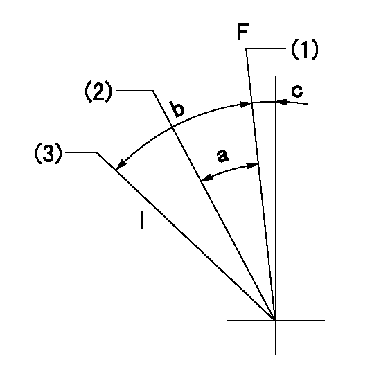
F:Full speed
I:Idle
(1)Set the speed at aa, set the stopper bolt
(2)Set the pump speed at bb.
(3)Stopper bolt setting
----------
aa=900r/min bb=750r/min
----------
a=4deg+-5deg b=18deg+-5deg c=2deg+-5deg
----------
aa=900r/min bb=750r/min
----------
a=4deg+-5deg b=18deg+-5deg c=2deg+-5deg
Stop lever angle
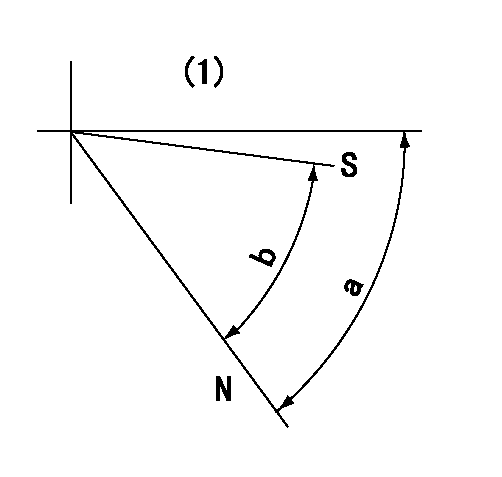
N:Pump normal
S:Stop the pump.
(1)No return spring
----------
----------
a=66.5deg+-5deg b=53deg+-5deg
----------
----------
a=66.5deg+-5deg b=53deg+-5deg
Timing setting

(1)Pump vertical direction
(2)Position of gear mark 'CC' at No 1 cylinder's beginning of injection
(3)B.T.D.C.: aa
(4)-
----------
aa=18deg
----------
a=(90deg)
----------
aa=18deg
----------
a=(90deg)
Information:
Unsolder the leads quickly to prevent heat from damaging the diodes.
(b) Remove the rectifiers mounting screws, then remove the rectifier.
Removing statorInspection
Key Points For Inspection(1) Inspection Rectifier
With each diode, measure the resistance between the diode terminal and the heat sink. Measure the resistance with the tester's (+) probe applied to the diode terminal and with the tester's (-) probe applied to the diode terminal. If the resistance is infinite in both cases, there is an open circuit. If the resistance is close to zero in both cases, there is a short circuit. An open circuit or short circuit indicates a diode fault. Replace the rectifiers if any diode is faulty.Next, measure the resistance between the terminals of the leads that connect the rectifier to the stator coil for each of the diodes. If any measurement reveals an open circuit (infinite resistance) or a short circuit (near-zero resistance), replace the rectifier.
Inspecting rectifier(2) Inspecting Field Coil
(a) Check whether continuity exists between the rotor's slip rings. If continuity does not exist, the field coil is open-circuited and the rotor must be replaced.
Field coil continuity test(b) Check whether continuity exists between each slip ring and the rotor shaft (or core). If continuity exists, the field coil is grounded and the rotor must be replaced.
Field coil ground test(3) Inspecting Stator Coils
(a) Check whether continuity exists between the leads at the ends of each stator coil. If continuity does not exist between any coil's leads, there is an open circuit and the stator must be replaced.
Stator coil continuity test(b) Check whether continuity exists between each stator coil lead and the stator core. If continuity exists, the stator coil is grounded and the stator must be replaced.
Stator coil ground test(4) Inspecting Brushes
(a) Replace the brush if it is worn down to the wear limit line.
Inspecting Brush(b) Disconnect the brush lead wires at the soldered sections to remove the brushes and springs.
Removing brushes and springs(c) To install new brushes, press them into the brush holders as shown in the diagram, then solder the lead wires.
Installing brushesAssembly
Follow the reverse of disassembly and use the procedure below:(1) The rear bearing has a groove for the snap ring. Install the snap ring in this groove. Make sure its tab is in the deep portion of the groove.(2) When installing the new rear bearing, place it in position with the side that has a groove toward the slip rings of the rotor.(3) To install the rear bearing in the rear bracket, heat the rear bracket.(4) Before installing the rotor in the rear bracket, insert a wire-shaped tooling into the hole in the rear bracket to lift the brushes of the slip rings. Remove the tooling after the rotor has been installed in position.
Assembling alternatorInstallation
Perform installation by following the removal sequence in reverse. Key Points For Installation(1) Install the fan belt on the alternator and mount the alternator on the engine. Temporarily tighten all the bolts.(2) Insert a bar between the alternator and crankcase. Using the bar as leverage, move the alternator