Information injection-pump assembly
ZEXEL
101602-7620
1016027620
ISUZU
1156028640
1156028640

Rating:
Service parts 101602-7620 INJECTION-PUMP ASSEMBLY:
1.
_
5.
AUTOM. ADVANCE MECHANIS
6.
COUPLING PLATE
8.
_
9.
_
11.
Nozzle and Holder
8-97016-146-1
12.
Open Pre:MPa(Kqf/cm2)
18.1{185}

15.
NOZZLE SET
Cross reference number
ZEXEL
101602-7620
1016027620
ISUZU
1156028640
1156028640
Zexel num
Bosch num
Firm num
Name
Calibration Data:
Adjustment conditions
Test oil
1404 Test oil ISO4113 or {SAEJ967d}
1404 Test oil ISO4113 or {SAEJ967d}
Test oil temperature
degC
40
40
45
Nozzle and nozzle holder
105780-8140
Bosch type code
EF8511/9A
Nozzle
105780-0000
Bosch type code
DN12SD12T
Nozzle holder
105780-2080
Bosch type code
EF8511/9
Opening pressure
MPa
17.2
Opening pressure
kgf/cm2
175
Injection pipe
Outer diameter - inner diameter - length (mm) mm 6-2-600
Outer diameter - inner diameter - length (mm) mm 6-2-600
Overflow valve
131424-4920
Overflow valve opening pressure
kPa
127
107
147
Overflow valve opening pressure
kgf/cm2
1.3
1.1
1.5
Tester oil delivery pressure
kPa
157
157
157
Tester oil delivery pressure
kgf/cm2
1.6
1.6
1.6
Direction of rotation (viewed from drive side)
Right R
Right R
Injection timing adjustment
Direction of rotation (viewed from drive side)
Right R
Right R
Injection order
1-5-3-6-
2-4
Pre-stroke
mm
3.4
3.35
3.45
Beginning of injection position
Drive side NO.1
Drive side NO.1
Difference between angles 1
Cal 1-5 deg. 60 59.5 60.5
Cal 1-5 deg. 60 59.5 60.5
Difference between angles 2
Cal 1-3 deg. 120 119.5 120.5
Cal 1-3 deg. 120 119.5 120.5
Difference between angles 3
Cal 1-6 deg. 180 179.5 180.5
Cal 1-6 deg. 180 179.5 180.5
Difference between angles 4
Cyl.1-2 deg. 240 239.5 240.5
Cyl.1-2 deg. 240 239.5 240.5
Difference between angles 5
Cal 1-4 deg. 300 299.5 300.5
Cal 1-4 deg. 300 299.5 300.5
Injection quantity adjustment
Adjusting point
A
Rack position
8.1
Pump speed
r/min
1100
1100
1100
Average injection quantity
mm3/st.
75.4
73.9
76.9
Max. variation between cylinders
%
0
-2.5
2.5
Basic
*
Fixing the lever
*
Injection quantity adjustment_02
Adjusting point
-
Rack position
5.3+-0.5
Pump speed
r/min
400
400
400
Average injection quantity
mm3/st.
9.4
8.1
10.7
Max. variation between cylinders
%
0
-14
14
Fixing the rack
*
Remarks
Adjust only variation between cylinders; adjust governor according to governor specifications.
Adjust only variation between cylinders; adjust governor according to governor specifications.
Test data Ex:
Governor adjustment
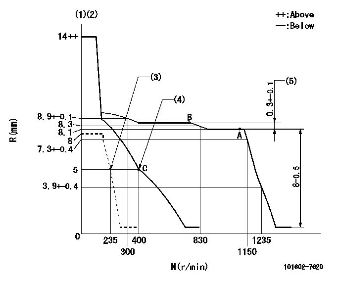
N:Pump speed
R:Rack position (mm)
(1)Target notch: K
(2)Tolerance for racks not indicated: +-0.05mm.
(3)Set idle sub-spring
(4)Main spring setting
(5)Rack difference between N = N1 and N = N2
----------
K=14 N1=1100r/min N2=750r/min
----------
----------
K=14 N1=1100r/min N2=750r/min
----------
Speed control lever angle
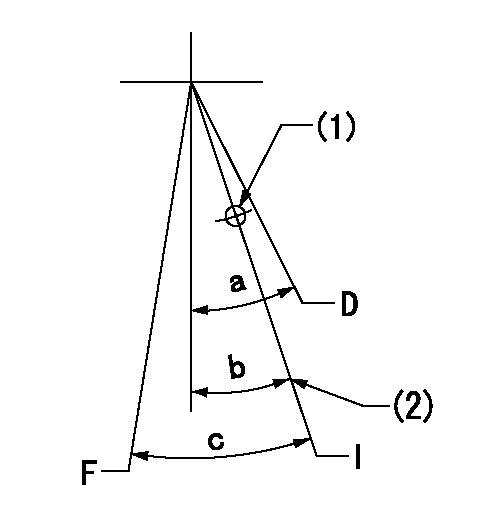
F:Full speed
I:Idle
D:Dead point
(1)Use the hole at R = aa
(2)Stopper bolt setting
----------
aa=70mm
----------
a=(20deg)+-3deg b=18deg+-1deg c=23deg+-5deg
----------
aa=70mm
----------
a=(20deg)+-3deg b=18deg+-1deg c=23deg+-5deg
Stop lever angle
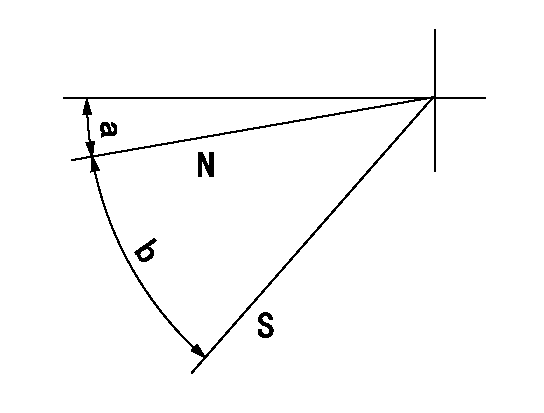
N:Pump normal
S:Stop the pump.
----------
----------
a=2.5deg+-5deg b=46deg+-5deg
----------
----------
a=2.5deg+-5deg b=46deg+-5deg
0000001501 LEVER
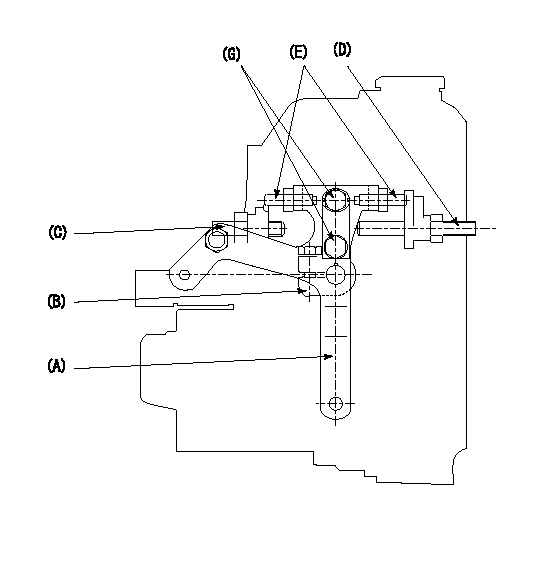
1. Variable lever adjustment
(1)Fix lever B in the idle position using the bolts C and D.
(2)Temporarily fix lever A in center of long hole.
(3)Set the dead point position temporarily and measure the lever angle.
(4)After idle adjustment, loosen the full side stopper bolt D.
(5)Move lever A in full speed direction.
(6)Fix the bolt D at the full speed position.
(7)Fix lever A using bolt E.
(8)(G) Lock using bolt.
(9)Finally, measure the lever angle and set the idle stopper bolt (C) stop position.
----------
----------
----------
----------
Timing setting

(1)Pump vertical direction
(2)Position of gear mark 'CC' at No 1 cylinder's beginning of injection
(3)B.T.D.C.: aa
(4)-
----------
aa=16deg
----------
a=(100deg)
----------
aa=16deg
----------
a=(100deg)
Information:
Overview of Radiator-Equipped Engine's Cooling System
Flow of coolantWater Pump
Removal and Inspection
Removal sequence and points to check on water pump(1) Cooling fan(2) Fan spacer(3) Water pump pulley(4) Fan belt(5) Water bypass hose(6) Water pump assembly Key Points for RemovalRemoval of the water pump pulley and fa belt is possible after loosening slightly both the adjusting bolt (1) and support bolt (2). This allows the alternator to be moved and then the V-belt slackened.
Removing water pump pulley Key Points for InspectionTurn the pump by hand to check the impeller shaft for smooth and quiet rotation. If irregular or noisy rotation is detected, replace them as an assembly.
Inspecting impeller and shaft rotationInstallation
Perform installation by following the removal sequence in reverse: Key Points for Inspection(1) Install the six water pump mounting bolts in their correct locations by referring to the figure on the right for the nominal diameters and lengths from bottom of head.
Correct locations of water pump mounting bolts(2) Use a new gasket when installing the water pump.(3) Adjust the fan belt tension according to the following specification.Unit: mm (in.)
Fan belt tension adjustmentThermostat
Disassembly
Removal sequence and points to check on the thermostat(1) Water hose(2) Water outlet fitting(3) Thermostat(4) Thermostat fitting(5) Thermo switchInspection
Key Points for Removal(1) Operation Test of Thermostat
Put the thermostat in a container of water. Heat the water and record both of the temperatures at which the valve starts to open and at which the valve lift reaches 8 mm (0.3 in.). If the readings do not conform to the specification below, replace the thermostat.
Operation test of thermostat
Carry out this operation with extreme care to avoid burns and prevent fire.
Installation
Except that the instructions shown below are to be followed, perform installation by following the removal sequence in reverse: Key Points for Inspection(1) Thermo Switch
Apply sealant to the threads an tighten to the specified torque.
Installing thermo switch(1) Thermostat
Make sure that the thermostat flange fits correctly into the counterbore in the thermostat fitting.
Installing thermostat