Information injection-pump assembly
BOSCH
9 400 614 907
9400614907
ZEXEL
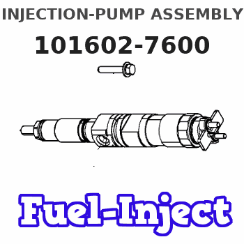
101602-7600
1016027600
ISUZU
1156028550
1156028550
Rating:
Service parts 101602-7600 INJECTION-PUMP ASSEMBLY:
1.
_
5.
AUTOM. ADVANCE MECHANIS
6.
COUPLING PLATE
8.
_
9.
_
11.
Nozzle and Holder
5-15300-107-1
12.
Open Pre:MPa(Kqf/cm2)
18.1{185}

15.
NOZZLE SET
Include in #1:
101602-7600
as INJECTION-PUMP ASSEMBLY
Include in #2:
104749-1231
as _
Cross reference number
Zexel num
Bosch num
Firm num
Name
101602-7600
9 400 614 907
1156028550 ISUZU
INJECTION-PUMP ASSEMBLY
6BG1 K
6BG1 K
Information:
Installing main bearings(b) Fit the flanged main bearing in the No. 3 journal position.(c) Smear a little engine oil on the inner surface of each bearing.
Installing flanged main bearingInstalling Crankshaft
(a) Wash the crankshaft thoroughly in cleaning solvent, then dry it with compressed air.(b) Keeping the crankshaft horizontal, gently lower it into the cylinder block.(c) Smear a little engine oil on each crankshaft journal.
Installing crankshaftInstalling Main Bearing Caps
(a) Before installing the main bearing caps, apply sealant to the mating surfaces of the frontmost and rearmost caps and to the corresponding surfaces in the cylinder block.
Installing main bearing caps(b) Referring to the cap numbers, fit the main bearing caps sequentially starting at the front of the engine. The arrow on each cap must point toward the front of the engine.
Front marks and cap numbers
Make sure the frontmost and rearmost caps fit flush against the cylinder block.
(4) Tightening Bearing Cap Bolts
Tighten the bearing cap bolts alternately a little at a time, then torque each bolt to specification.
Tightening bearing cap bolts(5) Checking Crankshaft Rotation
Confirm that the crankshaft turns smoothly.
Checking crankshaft rotation(6) Measuring End Plan of Crankshaft
Apply a dial gauge to the end of the crankshaft and measure the end play. If the measurement exceeds the specified limit, replace the No. 3 flanged bearing.
Measuring end play of crankshaft(7) Inserting Side Seals
(a) Apply sealant to the mating surfaces of each side seal. (b) With the radius of each side seal facing the outside, push the side seals part-way into the frontmost and rearmost caps by hand.
Alignment of side seals for installation(c) Press each side seal completely into position using a flat implement. Be careful not to bend the side seals.
Inserting side seals(8) Preparation for Installation of Piston and Connecting Rod Assemblies
(a) Clean each cylinder's inner surface with a rag, then smear each with engine oil.(b) Press the connecting rod bearings (upper and lower) into the connecting rods and caps such that the bearings' lugs fir into the grooves.(c) Smear the connecting rod bearings with engine oil.(d) Turn the cylinder block onto its side.
Preparation for installation of piston and connecting rod assemblies(9) Installing Piston and Connecting Rod Assemblies
(a) Smear the pistons' sliding surfaces and piston rings with engine oil(b) Position the piston ring gaps as shown in the illustration. Do not align any ring gap with the piston pin or at 90° to the piston pin.
Piston ring positions(c) Turn the crankshaft until the crank pin onto which the connecting rod is to be fitted reaches its TDC position.(d) Align the piston such that its front mark (this is stamped on the piston crown) points toward the timing gear case mounting surface (the front of the engine).(e) Using a piston guide (commercially available), insert the piston and connecting rod assembly into the cylinder from the top of the cylinder block.
Inserting piston and connecting rod assembly
If the piston is tapped hard while being inserted, the piston rings may break and the crank pin may become damaged.
(10) Installing Connecting Rod Caps
(a) When the connecting rod's big end is
Have questions with 101602-7600?
Group cross 101602-7600 ZEXEL
Isuzu
101602-7600
9 400 614 907
1156028550
INJECTION-PUMP ASSEMBLY
6BG1
6BG1