Information injection-pump assembly
BOSCH
9 400 611 432
9400611432
ZEXEL
101602-7580
1016027580
ISUZU
1156028540
1156028540
Rating:
Service parts 101602-7580 INJECTION-PUMP ASSEMBLY:
1.
_

5.
AUTOM. ADVANCE MECHANIS
6.
COUPLING PLATE
8.
_
9.
_
11.
Nozzle and Holder
5-15300-089-1
12.
Open Pre:MPa(Kqf/cm2)
18.1{185}

15.
NOZZLE SET
Include in #1:
101602-7580
as INJECTION-PUMP ASSEMBLY
Include in #2:
104749-1380
as _
Cross reference number
BOSCH
9 400 611 432
9400611432
ZEXEL
101602-7580
1016027580
ISUZU
1156028540
1156028540
Zexel num
Bosch num
Firm num
Name
101602-7580
9 400 611 432
1156028540 ISUZU
INJECTION-PUMP ASSEMBLY
6BD1 K 14BE INJECTION PUMP ASSY PE6A PE
6BD1 K 14BE INJECTION PUMP ASSY PE6A PE
Calibration Data:
Adjustment conditions
Test oil
1404 Test oil ISO4113 or {SAEJ967d}
1404 Test oil ISO4113 or {SAEJ967d}
Test oil temperature
degC
40
40
45
Nozzle and nozzle holder
105780-8140
Bosch type code
EF8511/9A
Nozzle
105780-0000
Bosch type code
DN12SD12T
Nozzle holder
105780-2080
Bosch type code
EF8511/9
Opening pressure
MPa
17.2
Opening pressure
kgf/cm2
175
Injection pipe
Outer diameter - inner diameter - length (mm) mm 6-2-600
Outer diameter - inner diameter - length (mm) mm 6-2-600
Overflow valve
132424-0620
Overflow valve opening pressure
kPa
157
123
191
Overflow valve opening pressure
kgf/cm2
1.6
1.25
1.95
Tester oil delivery pressure
kPa
157
157
157
Tester oil delivery pressure
kgf/cm2
1.6
1.6
1.6
Direction of rotation (viewed from drive side)
Right R
Right R
Injection timing adjustment
Direction of rotation (viewed from drive side)
Right R
Right R
Injection order
1-5-3-6-
2-4
Pre-stroke
mm
3.2
3.15
3.25
Beginning of injection position
Drive side NO.1
Drive side NO.1
Difference between angles 1
Cal 1-5 deg. 60 59.5 60.5
Cal 1-5 deg. 60 59.5 60.5
Difference between angles 2
Cal 1-3 deg. 120 119.5 120.5
Cal 1-3 deg. 120 119.5 120.5
Difference between angles 3
Cal 1-6 deg. 180 179.5 180.5
Cal 1-6 deg. 180 179.5 180.5
Difference between angles 4
Cyl.1-2 deg. 240 239.5 240.5
Cyl.1-2 deg. 240 239.5 240.5
Difference between angles 5
Cal 1-4 deg. 300 299.5 300.5
Cal 1-4 deg. 300 299.5 300.5
Injection quantity adjustment
Adjusting point
A
Rack position
8.9
Pump speed
r/min
1000
1000
1000
Average injection quantity
mm3/st.
73
71.5
74.5
Max. variation between cylinders
%
0
-2.5
2.5
Basic
*
Fixing the lever
*
Injection quantity adjustment_02
Adjusting point
B
Rack position
5.9+-0.5
Pump speed
r/min
300
300
300
Average injection quantity
mm3/st.
9.8
8.5
11.1
Max. variation between cylinders
%
0
-14
14
Fixing the rack
*
Test data Ex:
Governor adjustment
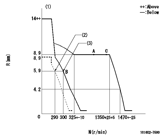
N:Pump speed
R:Rack position (mm)
(1)Target notch: K
(2)Set idle sub-spring
(3)Main spring setting
----------
K=4
----------
----------
K=4
----------
Speed control lever angle

F:Full speed
I:Idle
(1)Stopper bolt setting
----------
----------
a=7deg+-5deg b=29deg+-5deg
----------
----------
a=7deg+-5deg b=29deg+-5deg
Stop lever angle
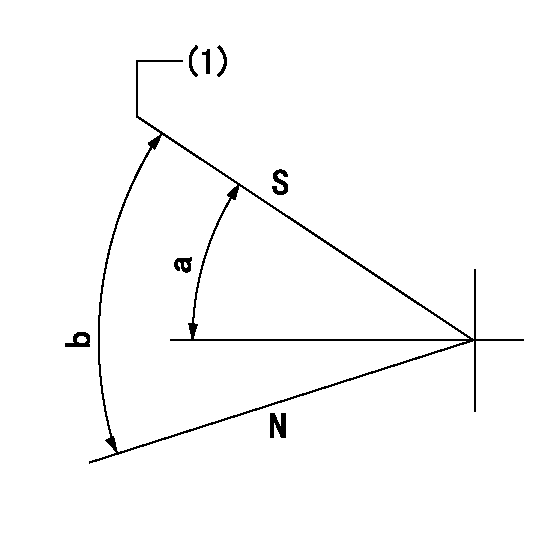
N:Pump normal
S:Stop the pump.
(1)Pump speed aa and rack position bb (to be sealed at delivery)
----------
aa=0r/min bb=1-0.2mm
----------
a=32deg+-5deg b=(55deg)
----------
aa=0r/min bb=1-0.2mm
----------
a=32deg+-5deg b=(55deg)
Timing setting

(1)Pump vertical direction
(2)Position of gear mark 'CC' at No 1 cylinder's beginning of injection
(3)B.T.D.C.: aa
(4)-
----------
aa=23deg
----------
a=(90deg)
----------
aa=23deg
----------
a=(90deg)
Information:
When fuel has stopped flowing out, turn the crankshaft slightly in the reverse direction such that fuel flows out. Then, slowly turn the crankshaft clockwise again to more accurately verify the point at which fuel stops flowing out.
End of fuel flow(c) If the IT mark on the crankshaft pulley and the mark on the gear case are aligned when fuel stops flowing out the injection timing is normal.
Timing marks(3) Adjustment
(a) If the injection timing is out of specification, make adjustments by increasing or decreasing the thickness of the injection pump's mounting shim. A change of 0.1 mm in the shim thickness yields a change of approximately 1° in the injection timing.
Injection timing adjusting shim(b) Increasing the shim thickness retards the injection timing, and decreasing the shim thickness advances it. Shims come in 9 different thicknesses from 0.2 mm (0.008 in.) to 1.0 mm (0.039 in.) at intervals of 0.1 mm (0.004 in.). The thickness is not indicated on the shim, so any shim should be measured with a vernier caliper before being used.
Before using any shim, apply sealant to both sides to prevent oil leakage.
(c) After making adjustments, check the injection timing is correct.(d) Close the cock on the fuel filter, then fit the delivery valve spring and injection pipe in their original positions.
Adjusting injection timingAdjusting Idle Speed
(1) Preparation for Adjustment
(a) Warm up the engine unit the coolant reaches a temperature of 60°C (140°F) or higher.(b) Make sure the valve clearances, injection timing, and injectors are normal.(2) Adjusting Low-Idle Speed
Loosen the locknut on the idling set bolt, turn the bolt to achieve the specified low-idle speed (1000 25min-1), then tighten the lock nut to hold the bolt in that position.(3) Adjusting No-Load Maximum Speed
Loosen the lock nut on the high-speed set bolt, turn the bolt to achieve the specified no-load maximum speed (2600 +30-10 min-1), then tighten the lock nut to hold the bolt in that position.
Adjusting idle speedAdjusting Fan Belt Tension
(1) Press the fan belt with the specified force mid-way between the alternator pulley and crankshaft pulley, and observe the extent of deflection.Unit: mm (in.) (2) If the extent of deflection is out of specification, loosen the adjusting bolt and adjust the fan belt tension by moving the alternator. Retighten the adjusting bolt securely.
Adjusting fan belt tensionRunning in the Engine
After an overhaul, the engine should be tested and inspected on a dynamometer. This operation serves to run in the engine's major moving parts.Starting the Engine
(1) Before starting the engine, check the coolant, engine oil and fuel levels and bleed all air out of the fuel and cooling systems.(2) Without supplying fuel to the engine, crank the engine for about 10 seconds to permit oil to circulate through it.(3) Move the speed control lever slightly in the fuel-increase direction. (Do not move the lever to the full-injection position.) Then, turn the starter switch to the START position to start the engine.(4) Once the engine has started, set it to the low-idle speed using the speed control lever.Inspection after
Have questions with 101602-7580?
Group cross 101602-7580 ZEXEL
Isuzu
101602-7580
9 400 611 432
1156028540
INJECTION-PUMP ASSEMBLY
6BD1
6BD1