Information injection-pump assembly
ZEXEL
101602-7490
1016027490
ISUZU
1156028000
1156028000
Rating:
Service parts 101602-7490 INJECTION-PUMP ASSEMBLY:
1.
_

5.
AUTOM. ADVANCE MECHANIS
6.
COUPLING PLATE
8.
_
9.
_
11.
Nozzle and Holder
5-15300-089-1
12.
Open Pre:MPa(Kqf/cm2)
18.1{185}

15.
NOZZLE SET
Include in #1:
101602-7490
as INJECTION-PUMP ASSEMBLY
Include in #2:
104748-1020
as _
Cross reference number
ZEXEL
101602-7490
1016027490
ISUZU
1156028000
1156028000
Zexel num
Bosch num
Firm num
Name
Calibration Data:
Adjustment conditions
Test oil
1404 Test oil ISO4113 or {SAEJ967d}
1404 Test oil ISO4113 or {SAEJ967d}
Test oil temperature
degC
40
40
45
Nozzle and nozzle holder
105780-8140
Bosch type code
EF8511/9A
Nozzle
105780-0000
Bosch type code
DN12SD12T
Nozzle holder
105780-2080
Bosch type code
EF8511/9
Opening pressure
MPa
17.2
Opening pressure
kgf/cm2
175
Injection pipe
Outer diameter - inner diameter - length (mm) mm 6-2-600
Outer diameter - inner diameter - length (mm) mm 6-2-600
Overflow valve opening pressure
kPa
157
123
191
Overflow valve opening pressure
kgf/cm2
1.6
1.25
1.95
Tester oil delivery pressure
kPa
157
157
157
Tester oil delivery pressure
kgf/cm2
1.6
1.6
1.6
Direction of rotation (viewed from drive side)
Right R
Right R
Injection timing adjustment
Direction of rotation (viewed from drive side)
Right R
Right R
Injection order
1-5-3-6-
2-4
Pre-stroke
mm
3.6
3.55
3.65
Beginning of injection position
Drive side NO.1
Drive side NO.1
Difference between angles 1
Cal 1-5 deg. 60 59.5 60.5
Cal 1-5 deg. 60 59.5 60.5
Difference between angles 2
Cal 1-3 deg. 120 119.5 120.5
Cal 1-3 deg. 120 119.5 120.5
Difference between angles 3
Cal 1-6 deg. 180 179.5 180.5
Cal 1-6 deg. 180 179.5 180.5
Difference between angles 4
Cyl.1-2 deg. 240 239.5 240.5
Cyl.1-2 deg. 240 239.5 240.5
Difference between angles 5
Cal 1-4 deg. 300 299.5 300.5
Cal 1-4 deg. 300 299.5 300.5
Injection quantity adjustment
Adjusting point
A
Rack position
8.9
Pump speed
r/min
800
800
800
Average injection quantity
mm3/st.
56.5
55
58
Max. variation between cylinders
%
0
-2
2
Basic
*
Fixing the lever
*
Injection quantity adjustment_02
Adjusting point
B
Rack position
8.6
Pump speed
r/min
1400
1400
1400
Average injection quantity
mm3/st.
58.8
56.8
60.8
Max. variation between cylinders
%
0
-4
4
Fixing the lever
*
Injection quantity adjustment_03
Adjusting point
-
Rack position
6.5+-0.5
Pump speed
r/min
325
325
325
Average injection quantity
mm3/st.
9.4
8
10.8
Max. variation between cylinders
%
0
-14
14
Fixing the rack
*
Remarks
Adjust only variation between cylinders; adjust governor according to governor specifications.
Adjust only variation between cylinders; adjust governor according to governor specifications.
Test data Ex:
Governor adjustment
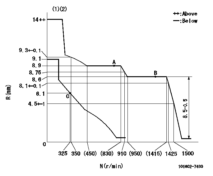
N:Pump speed
R:Rack position (mm)
(1)Target notch: K
(2)Tolerance for racks not indicated: +-0.05mm.
----------
K=13
----------
----------
K=13
----------
Speed control lever angle
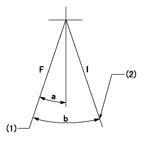
F:Full speed
I:Idle
(1)Set the pump speed at aa. ( At delivery )
(2)Stopper bolt setting
----------
aa=1400r/min
----------
a=17deg+-5deg b=32deg+-5deg
----------
aa=1400r/min
----------
a=17deg+-5deg b=32deg+-5deg
Stop lever angle
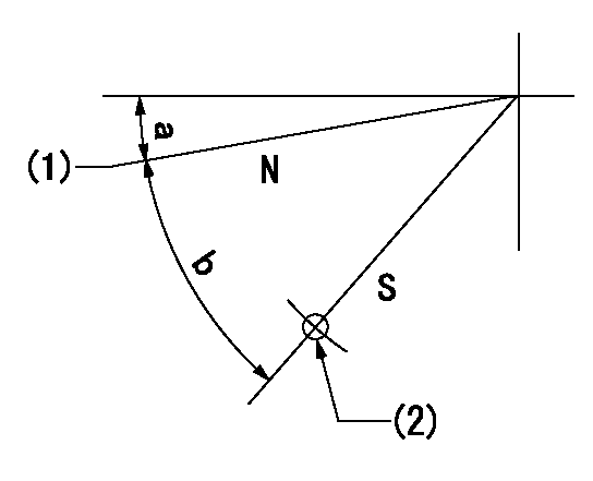
N:Pump normal
S:Stop the pump.
(1)Normal
(2)Use the hole at R = aa
----------
aa=37.12mm
----------
a=2.5deg+-5deg b=46deg+-5deg
----------
aa=37.12mm
----------
a=2.5deg+-5deg b=46deg+-5deg
Timing setting

(1)Pump vertical direction
(2)Position of gear mark 'CC' at No 1 cylinder's beginning of injection
(3)B.T.D.C.: aa
(4)-
----------
aa=20deg
----------
a=(90deg)
----------
aa=20deg
----------
a=(90deg)
Information:
3. Inspection
Inspection points4. Assembly
Assembly sequenceFollow the reverse of disassembly and use the procedure that follows. Assembly procedure (1) Barrel installationPut each barrel in position in the housing with its slot in alignment with the dowel of the housing and put it straight down into the bore. If the slot in the barrel is not aligned with the dowel of the housing, the O-ring will not seat correctly (still visible) after the delivery valve holder has been installed.
Installing barrels(2) Delivery valve installationInstall the delivery valve, gasket, spring and O-ring on the barrel and tighten the delivery valve holder finger tight. Do this step for remainder of the delivery valves.
a) Any time the injection pump is disassembled, a new O-ring must be installed.b) Make sure the threads of the delivery valve holder do not cause damage to the O-rings.
Installing delivery valves(3) Control sleeve installation (a) Install each control sleeve with the center tooth in alignment with the line mark of the control rack.
Installing control sleeves(b) Put the plungers in position in the barrels.
Make sure the notch in the plunger is toward the adjusting plate.
Installing plungers(4) Tappet installationMove the control rack back and forth while pushing down on each tappet to align the slot in the tappet with the hole in the housing for the tappet guide pin. Install the lock plates and tappet guide pins in position.
Any time the injection pump is disassembled, new lock plates must be used.
Installing tappets(5) Delivery valve holder installation Put the delivery valve holders in position and tighten them to the specified torque.
Do not over tighten the delivery valve holders. This can put end force on the barrels, resulting in a failure of the plungers to move freely. If the holders are not tightened to the specified torque, engine oil would leak in the injection pump.
Tightening delivery valve holders(6) Inspection after assembly (a) After the injection pump has been assembled, check to see if the control rack moves freely without any binding or catching.(b) If the control rack fails to move freely, the possible causes are:1) Pumping element(s) sticking2) Foreign particles lodged between control rack and sleeves3) Over-tightening of delivery valve holder(s)Disassemble and check the injection pump to locate the cause of the trouble. (c) After the injection pump has been finally assembled, check the injection timing.
Checking control rack movementGOVERNOR
1. Disassembly and inspection
Disassembly sequence and inspection points1 Tie rod spring2 Tie rod3 Speed control lever4 Spring pin5 Grooved pin6 Governor shaft (Remove 7 thru 11 as an assembly.)7 Governor lever8 Start spring9 Tension lever10 Governor spring11 Governor spring lever12 Governor case2. Assembly (1) Install the levers in position.
Installing governor levers(2) Put O-ring on the governor shaft. (3) Put the governor shaft in position in the governor case and put the levers on the governor shaft. (4) Install the grooved pin and spring pin in position with a hammer.(5) Install the tie rod and tie rod spring in position.
Assembling governor3. Torque spring set installation The torque spring set is to be installed and adjusted after an