Information injection-pump assembly
ZEXEL
101602-7470
1016027470
ISUZU
1156027960
1156027960
Rating:
Service parts 101602-7470 INJECTION-PUMP ASSEMBLY:
1.
_
5.
AUTOM. ADVANCE MECHANIS
7.
COUPLING PLATE
8.
_
9.
_
11.
Nozzle and Holder
1-15300-247-1
12.
Open Pre:MPa(Kqf/cm2)
18.1{185}

15.
NOZZLE SET
Cross reference number
ZEXEL
101602-7470
1016027470
ISUZU
1156027960
1156027960
Zexel num
Bosch num
Firm num
Name
Calibration Data:
Adjustment conditions
Test oil
1404 Test oil ISO4113 or {SAEJ967d}
1404 Test oil ISO4113 or {SAEJ967d}
Test oil temperature
degC
40
40
45
Nozzle and nozzle holder
105780-8140
Bosch type code
EF8511/9A
Nozzle
105780-0000
Bosch type code
DN12SD12T
Nozzle holder
105780-2080
Bosch type code
EF8511/9
Opening pressure
MPa
17.2
Opening pressure
kgf/cm2
175
Injection pipe
Outer diameter - inner diameter - length (mm) mm 6-2-600
Outer diameter - inner diameter - length (mm) mm 6-2-600
Overflow valve
131424-4920
Overflow valve opening pressure
kPa
127
107
147
Overflow valve opening pressure
kgf/cm2
1.3
1.1
1.5
Tester oil delivery pressure
kPa
157
157
157
Tester oil delivery pressure
kgf/cm2
1.6
1.6
1.6
Direction of rotation (viewed from drive side)
Right R
Right R
Injection timing adjustment
Direction of rotation (viewed from drive side)
Right R
Right R
Injection order
1-5-3-6-
2-4
Pre-stroke
mm
3.6
3.55
3.65
Beginning of injection position
Drive side NO.1
Drive side NO.1
Difference between angles 1
Cal 1-5 deg. 60 59.5 60.5
Cal 1-5 deg. 60 59.5 60.5
Difference between angles 2
Cal 1-3 deg. 120 119.5 120.5
Cal 1-3 deg. 120 119.5 120.5
Difference between angles 3
Cal 1-6 deg. 180 179.5 180.5
Cal 1-6 deg. 180 179.5 180.5
Difference between angles 4
Cyl.1-2 deg. 240 239.5 240.5
Cyl.1-2 deg. 240 239.5 240.5
Difference between angles 5
Cal 1-4 deg. 300 299.5 300.5
Cal 1-4 deg. 300 299.5 300.5
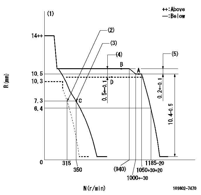
Injection quantity adjustment
Adjusting point
A
Rack position
10.5
Pump speed
r/min
1050
1050
1050
Average injection quantity
mm3/st.
86.3
84.8
87.8
Max. variation between cylinders
%
0
-2.5
2.5
Basic
*
Fixing the lever
*
Boost pressure
kPa
33.3
33.3
Boost pressure
mmHg
250
250
Injection quantity adjustment_02
Adjusting point
C
Rack position
7.3+-0.5
Pump speed
r/min
350
350
350
Average injection quantity
mm3/st.
10.8
9.5
12.1
Max. variation between cylinders
%
0
-14
14
Fixing the rack
*
Boost pressure
kPa
0
0
0
Boost pressure
mmHg
0
0
0
Boost compensator adjustment
Pump speed
r/min
700
700
700
Rack position
10.2
Boost pressure
kPa
9.3
6.6
12
Boost pressure
mmHg
70
50
90
Boost compensator adjustment_02
Pump speed
r/min
700
700
700
Rack position
10.7
Boost pressure
kPa
21.3
16
26.6
Boost pressure
mmHg
160
120
200
Test data Ex:
Governor adjustment
N:Pump speed
R:Rack position (mm)
(1)Target notch: K
(2)Set idle sub-spring
(3)Main spring setting
(4)Boost compensator stroke
(5)Rack difference between N = N1 and N = N2
----------
K=8 N1=1050r/min N2=850r/min
----------
----------
K=8 N1=1050r/min N2=850r/min
----------
Speed control lever angle

F:Full speed
I:Idle
(1)Stopper bolt setting
----------
----------
a=0deg+-5deg b=21deg+-5deg
----------
----------
a=0deg+-5deg b=21deg+-5deg
Stop lever angle

N:Pump normal
S:Stop the pump.
----------
----------
a=12deg+-5deg b=46deg+-5deg
----------
----------
a=12deg+-5deg b=46deg+-5deg
Timing setting

(1)Pump vertical direction
(2)Position of coupling's threaded hole at No 1 cylinder's beginning of injection
(3)B.T.D.C.: aa
(4)-
----------
aa=15deg
----------
a=(60deg)
----------
aa=15deg
----------
a=(60deg)
Information:
Testing field coil for open circuit(b) Test for no continuity between the slip ring and shaft (or core) as shown in the illustration. Any continuity shows there is a grounded circuit in the field coil. Replace the field coil.
Testing field coil for grounded circuit(3) Stator core(a) Test for continuity between the leads as shown in the illustration. No continuity shows there is an open circuit in the stator core. Replace the stator core.
Testing stator core for open circuit(b) Test for no continuity between each lead and stator core as shown in the illustration. Any continuity shows there is a grounded circuit in the stator core. Replace the stator core.
Testing stator core for grounded circuit(4) Brushes(a) Make replacement of brushes that have been worn down to, or beyond, the wear limit line.
Checking brush for wear(b) To remove the brushes from the brush holder for replacement, unsolder the leads from the brushes. This will permit removal of the brushes and springs.
Removing brushes for replacementTo install the new brushes, put them in position in the brush holder and solder the leads to the brushes.
Installing new brushes3. AssemblyFollow the reverse of disassembly and use the procedure that follows. (a) The rear bearing has a groove for the snap ring. Install the snap ring in this groove, make sure its tab is in the deep portion of the groove.(b) When installing the new rear bearing, put it in position with the side that has a groove toward the slip rings of the rotor.(c) To install the rear bearing in the rear bracket, heat the rear bracket.(d) Before installing the rotor in the rear bracket, insert a wire-shaped tooling into the hole in the rear bracket to lift the brushes off the slip rings. Remove the tooling after the rotor has been installed in position.
Assembling alternatorKEY SHUTOFF SYSTEM (ETS solenoid type)
1. GeneralThis system, consisting of a switch, a control timer and a solenoid, permits the operator to shut off the engine by turning the starter switch key to OFF position. Another function of this system is to shut off the engine automatically when the oil pressure is too low, or when coolant temperature is too high.
Key shutoff system2. Cord color (standard)
Control timer connection3. Shutoff solenoid installation (a) Remove the tie rod cover. (b) Coat the threads of the stop solenoid with thread sealant (Three Bond 1212). Coat the length of the threads to be turned in the governor case. (c) Temporarily install the shutoff solenoid and nut in the governor case.(d) Move the injection pump control rack all the way to the non-injection (shutoff) position.(c) Turn the shutoff solenoid in the governor case while pushing the plunger toward the control rack until the shaft is in touch with the tie rod. At this time, clearance C must be 0 mm. (Under this condition, the plunger will be rotated by the shutoff solenoid being turned in.)(f) Back off the shutoff solenoid 30° to 45° turn (the clearance between the control rack and plunger will be