Information injection-pump assembly
ZEXEL
101602-7460
1016027460
ISUZU
1156027840
1156027840
Rating:
Cross reference number
ZEXEL
101602-7460
1016027460
ISUZU
1156027840
1156027840
Zexel num
Bosch num
Firm num
Name
Calibration Data:
Adjustment conditions
Test oil
1404 Test oil ISO4113 or {SAEJ967d}
1404 Test oil ISO4113 or {SAEJ967d}
Test oil temperature
degC
40
40
45
Nozzle and nozzle holder
105780-8140
Bosch type code
EF8511/9A
Nozzle
105780-0000
Bosch type code
DN12SD12T
Nozzle holder
105780-2080
Bosch type code
EF8511/9
Opening pressure
MPa
17.2
Opening pressure
kgf/cm2
175
Injection pipe
Outer diameter - inner diameter - length (mm) mm 6-2-600
Outer diameter - inner diameter - length (mm) mm 6-2-600
Overflow valve
131424-4920
Overflow valve opening pressure
kPa
127
107
147
Overflow valve opening pressure
kgf/cm2
1.3
1.1
1.5
Tester oil delivery pressure
kPa
157
157
157
Tester oil delivery pressure
kgf/cm2
1.6
1.6
1.6
Direction of rotation (viewed from drive side)
Right R
Right R
Injection timing adjustment
Direction of rotation (viewed from drive side)
Right R
Right R
Injection order
1-5-3-6-
2-4
Pre-stroke
mm
3.4
3.35
3.45
Beginning of injection position
Drive side NO.1
Drive side NO.1
Difference between angles 1
Cal 1-5 deg. 60 59.5 60.5
Cal 1-5 deg. 60 59.5 60.5
Difference between angles 2
Cal 1-3 deg. 120 119.5 120.5
Cal 1-3 deg. 120 119.5 120.5
Difference between angles 3
Cal 1-6 deg. 180 179.5 180.5
Cal 1-6 deg. 180 179.5 180.5
Difference between angles 4
Cyl.1-2 deg. 240 239.5 240.5
Cyl.1-2 deg. 240 239.5 240.5
Difference between angles 5
Cal 1-4 deg. 300 299.5 300.5
Cal 1-4 deg. 300 299.5 300.5
Injection quantity adjustment
Adjusting point
A
Rack position
8.4
Pump speed
r/min
1000
1000
1000
Average injection quantity
mm3/st.
74.8
73.3
76.3
Max. variation between cylinders
%
0
-2.5
2.5
Basic
*
Fixing the lever
*
Injection quantity adjustment_02
Adjusting point
-
Rack position
5.6+-0.5
Pump speed
r/min
340
340
340
Average injection quantity
mm3/st.
9.4
8.1
10.7
Max. variation between cylinders
%
0
-14
14
Fixing the rack
*
Remarks
Adjust only variation between cylinders; adjust governor according to governor specifications.
Adjust only variation between cylinders; adjust governor according to governor specifications.
Test data Ex:
Governor adjustment
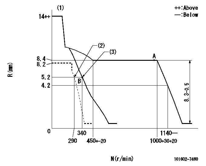
N:Pump speed
R:Rack position (mm)
(1)Target notch: K
(2)Set idle sub-spring
(3)Main spring setting
----------
K=14
----------
----------
K=14
----------
Speed control lever angle
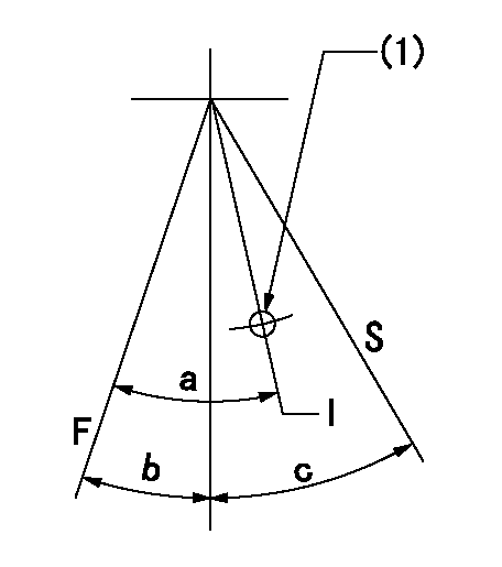
F:Full speed
I:Idle
S:Stop
(1)Use the hole at R = aa
----------
aa=70mm
----------
a=20deg+-5deg b=3deg+-5deg c=35deg+-3deg
----------
aa=70mm
----------
a=20deg+-5deg b=3deg+-5deg c=35deg+-3deg
Stop lever angle

N:Pump normal
S:Stop the pump.
----------
----------
a=12deg+-5deg b=46deg+-5deg
----------
----------
a=12deg+-5deg b=46deg+-5deg
Timing setting

(1)Pump vertical direction
(2)Position of gear mark 'CC' at No 1 cylinder's beginning of injection
(3)B.T.D.C.: aa
(4)-
----------
aa=16deg
----------
a=(100deg)
----------
aa=16deg
----------
a=(100deg)
Information:
Unit: mm (in.)
Measuring clearance between piston ring and groove(b) If the clearance still exceeds the limit after new piston rings have been installed, replace the piston.(3) Clearance between ends of piston ring Put the piston ring in a gauge or in the bore in a new cylinder block and measure the clearance between the ends of the ring with a feeler gauge as shown in the illustration. If the gauge as shown in the illustration. If the clearance exceeds the limit, replace all the rings.
Measuring clearance between ends of piston ring Put the piston ring in the gauge or cylinder squarely with the piston.
Unit: mm (in.)(4) Clearance between piston pin and piston Measure the diameter of the piston pin and the bore in the piston for the pin as shown in the illustration to find the clearance. If the clearance exceeds the limit, replace the piston or pin whichever is badly worn.
Unit: mm (in.)
Measuring piston pin and bore in piston for pin2. Connecting rods Check the connecting rod for bend or twist as follows:(a) Measure "C" and "l". If "C" exceeds 0.05 mm (0.0020 in.) per 100 mm (3.94 in.) of "l", straighten the connecting rod with a press.
Unit: mm (in.)
Checking connecting rod for bend or twist(b) Generally, a connecting rod aligner is used to check the connecting rod for bend or twist. To check the rod for bend, install the cap to the connecting rod and tighten the cap nuts to the specified torque.
Check connecting rod on a connecting rod aligner(c) To check the connecting rod fitted to the piston for bend, put the connecting rod and piston on the surface plate as shown in the illustration, insert a round bear having a diameter equal to that of the crankpin into the bore in the big end of the rod and measure "A" and "B" with a dial indicator. Subtract "A" from "B" to find the bend ("C").
Checking connecting rod for bend with a dial indicator 3. Crankshaft(1) Clearance between crankpin and connecting rod bearing(a) Install the bearing (upper and lower halves) and cap to the big end of the connecting rod and tighten the cap nuts to the specified torque. Measure the bore in the bearing for crankpin as shown in the illustration. (b) Measure the diameter of the crankpin as shown in the illustration to find the clearance between the crankpin and connecting rod bearing.
Unit: mm (in.)
Measuring diameter of crankpin(c) If the clearance exceeds the limit, install a new bearing and check the clearance again. (d) If the clearance still exceeds the limit, grind the crankpin to 0.25 mm (0.0098 in.), 0.50 mm (0.0197 in.) or 0.75 mm (0.0295 in.) undersize and use undersize connecting rod bearing.Crankpin undersizes
Unit: mm (in.)
a) Grind all the crankpins of one crankshaft to the same undersize.b) Finish the crankpin fillets to a radius of 2.5 mm (0.098 in.).
Crankpin fillet radius(2) Clearance between journal and main bearing (a) Install the main bearing (upper and lower halves) and cap to the cylinder