Information injection-pump assembly
BOSCH
F 019 Z10 265
f019z10265
ZEXEL
101602-7440
1016027440
ISUZU
1156018200
1156018200
Rating:
Service parts 101602-7440 INJECTION-PUMP ASSEMBLY:
1.
_
5.
AUTOM. ADVANCE MECHANIS
6.
COUPLING PLATE
8.
_
9.
_
11.
Nozzle and Holder
1-15300-104-2
12.
Open Pre:MPa(Kqf/cm2)
18.1{185}

15.
NOZZLE SET
Cross reference number
BOSCH
F 019 Z10 265
f019z10265
ZEXEL
101602-7440
1016027440
ISUZU
1156018200
1156018200
Zexel num
Bosch num
Firm num
Name
F 019 Z10 265
1156018200 ISUZU
INJECTION-PUMP ASSEMBLY
6BG1 * K 14BE PE6A PE
6BG1 * K 14BE PE6A PE
Calibration Data:
Adjustment conditions
Test oil
1404 Test oil ISO4113 or {SAEJ967d}
1404 Test oil ISO4113 or {SAEJ967d}
Test oil temperature
degC
40
40
45
Nozzle and nozzle holder
105780-8140
Bosch type code
EF8511/9A
Nozzle
105780-0000
Bosch type code
DN12SD12T
Nozzle holder
105780-2080
Bosch type code
EF8511/9
Opening pressure
MPa
17.2
Opening pressure
kgf/cm2
175
Injection pipe
Outer diameter - inner diameter - length (mm) mm 6-2-600
Outer diameter - inner diameter - length (mm) mm 6-2-600
Overflow valve opening pressure
kPa
157
123
191
Overflow valve opening pressure
kgf/cm2
1.6
1.25
1.95
Tester oil delivery pressure
kPa
157
157
157
Tester oil delivery pressure
kgf/cm2
1.6
1.6
1.6
Direction of rotation (viewed from drive side)
Right R
Right R
Injection timing adjustment
Direction of rotation (viewed from drive side)
Right R
Right R
Injection order
1-5-3-6-
2-4
Pre-stroke
mm
3.6
3.55
3.65
Beginning of injection position
Drive side NO.1
Drive side NO.1
Difference between angles 1
Cal 1-5 deg. 60 59.5 60.5
Cal 1-5 deg. 60 59.5 60.5
Difference between angles 2
Cal 1-3 deg. 120 119.5 120.5
Cal 1-3 deg. 120 119.5 120.5
Difference between angles 3
Cal 1-6 deg. 180 179.5 180.5
Cal 1-6 deg. 180 179.5 180.5
Difference between angles 4
Cyl.1-2 deg. 240 239.5 240.5
Cyl.1-2 deg. 240 239.5 240.5
Difference between angles 5
Cal 1-4 deg. 300 299.5 300.5
Cal 1-4 deg. 300 299.5 300.5
Injection quantity adjustment
Adjusting point
A
Rack position
9.5
Pump speed
r/min
800
800
800
Average injection quantity
mm3/st.
67.5
66
69
Max. variation between cylinders
%
0
-2
2
Basic
*
Fixing the lever
*
Injection quantity adjustment_02
Adjusting point
C
Rack position
6.1+-0.5
Pump speed
r/min
325
325
325
Average injection quantity
mm3/st.
8.5
7.1
9.9
Max. variation between cylinders
%
0
-14
14
Fixing the rack
*
Test data Ex:
Governor adjustment
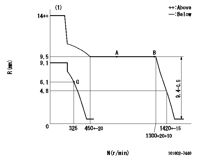
N:Pump speed
R:Rack position (mm)
(1)Target notch: K
----------
K=12
----------
----------
K=12
----------
Speed control lever angle

F:Full speed
I:Idle
(1)Stopper bolt setting
----------
----------
a=9deg+-5deg b=28deg+-5deg
----------
----------
a=9deg+-5deg b=28deg+-5deg
Stop lever angle

N:Pump normal
S:Stop the pump.
----------
----------
a=12deg+-5deg b=46deg+-5deg
----------
----------
a=12deg+-5deg b=46deg+-5deg
Timing setting

(1)Pump vertical direction
(2)Position of gear mark 'CC' at No 1 cylinder's beginning of injection
(3)B.T.D.C.: aa
(4)-
----------
aa=20deg
----------
a=(90deg)
----------
aa=20deg
----------
a=(90deg)
Information:
COMPRESSION PRESSURE MEASUREMENT
1. Inspection Check to make sure -(1) The crankcase oil level is correct, and the air cleaner, starter and battery are all in normal condition.(2) The engine is at the normal operating temperature.2. Measurement (1) Move the control lever to a position for shutting off fuel supply.(2) Remove all glow plugs from the engine. Install the compression gauge and adapter (ST332270) combination to a cylinder on which the compression pressure is to be measured.
Compression gauge and adaptor
Measuring compression pressure(3) Turn the engine with the starter and read the gauge pressure at the instant the gauge pointer comes to stop.(4) If the gauge reading is below the limit, overhaul the engine.
a) Be sure to measure the compression pressure on all cylinders.b) The compression pressure varies with change of engine rpm. This makes it necessary to check engine rpm at the time of measuring the compression pressure.
a) It is important to measure the compression pressure at regular intervals to obtain the data on the gradual change of the compression pressure.b) The compression pressure would be slightly higher than the standard in a new or overhauled engine owing to break-in of the piston rings, valve seats, etc. It drops as the engine components wear down.
TROUBLESHOOTING
1. GeneralThe diagnosis of troubles, especially those caused by a faulty fuel injection pump or injection nozzles, or low compression pressure, can be difficult. It requires a careful inspection to determine not which item is the cause, but how many causes are contributing to the cause. Several causes may be contributing to a single trouble.On the following pages, there are troubleshooting charts on which engine troubles can be traced to their causes. Each chart has items to be verified ahead and suggested inspection procedure.Diesel engines exhibit some marked characteristics during operation. Knowing these characteristics will help minimize time lost in tracing engine troubles to their source. Following are the characteristics of diesel engines you should know about for diagnosis:* Combustion know (diesel knock)* Some black exhaust smoke (when the engine picks up load)* Vibration (due to high compression pressure and high torque)* Hunting (when the engine speed is quickly decreased)* Some white exhaust smoke (when the engine is cold, or shortly after the engine has been started) 2. Engine troubleshooting Problem 1: Hard starting(1) Items to be checked for ahead* Clogged air cleaner* Wrong oil grade for weather conditions * Poor quality fuel* Low cranking speed(2) Inspection procedure Problem 2: Fuel knockMore or less fuel knock occurs in diesel engines. This may be caused either by an excessively large delay period or by a too fast rate of fuel injection.(1) Items to be checked for ahead* Clogged air cleaner* Poor quality fuel(2) Inspection procedure Problem 3: Overheating(1) Items to be checked for aheadOverheating might also be caused by abnormal operating conditions. If the engine is overheating but its cooling system is not contributing to this trouble, it is necessary to check the difference between the ambient temperature and coolant temperature when the engine is in