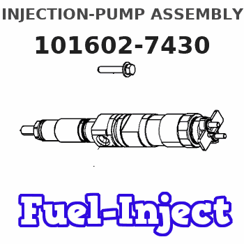
Information injection-pump assembly
ZEXEL
101602-7430
1016027430
ISUZU
1156027420
1156027420
Rating:
Service parts 101602-7430 INJECTION-PUMP ASSEMBLY:
1.
_
5.
AUTOM. ADVANCE MECHANIS
7.
COUPLING PLATE
8.
_
9.
_
11.
Nozzle and Holder
1-15300-247-1
12.
Open Pre:MPa(Kqf/cm2)
18.1{185}

15.
NOZZLE SET
Cross reference number
ZEXEL
101602-7430
1016027430
ISUZU
1156027420
1156027420
Zexel num
Bosch num
Firm num
Name
Calibration Data:
Adjustment conditions
Test oil
1404 Test oil ISO4113 or {SAEJ967d}
1404 Test oil ISO4113 or {SAEJ967d}
Test oil temperature
degC
40
40
45
Nozzle and nozzle holder
105780-8140
Bosch type code
EF8511/9A
Nozzle
105780-0000
Bosch type code
DN12SD12T
Nozzle holder
105780-2080
Bosch type code
EF8511/9
Opening pressure
MPa
17.2
Opening pressure
kgf/cm2
175
Injection pipe
Outer diameter - inner diameter - length (mm) mm 6-2-600
Outer diameter - inner diameter - length (mm) mm 6-2-600
Overflow valve
131424-4920
Overflow valve opening pressure
kPa
127
107
147
Overflow valve opening pressure
kgf/cm2
1.3
1.1
1.5
Tester oil delivery pressure
kPa
157
157
157
Tester oil delivery pressure
kgf/cm2
1.6
1.6
1.6
Direction of rotation (viewed from drive side)
Right R
Right R
Injection timing adjustment
Direction of rotation (viewed from drive side)
Right R
Right R
Injection order
1-5-3-6-
2-4
Pre-stroke
mm
3.6
3.55
3.65
Beginning of injection position
Drive side NO.1
Drive side NO.1
Difference between angles 1
Cal 1-5 deg. 60 59.5 60.5
Cal 1-5 deg. 60 59.5 60.5
Difference between angles 2
Cal 1-3 deg. 120 119.5 120.5
Cal 1-3 deg. 120 119.5 120.5
Difference between angles 3
Cal 1-6 deg. 180 179.5 180.5
Cal 1-6 deg. 180 179.5 180.5
Difference between angles 4
Cyl.1-2 deg. 240 239.5 240.5
Cyl.1-2 deg. 240 239.5 240.5
Difference between angles 5
Cal 1-4 deg. 300 299.5 300.5
Cal 1-4 deg. 300 299.5 300.5
Injection quantity adjustment
Adjusting point
A
Rack position
10.6
Pump speed
r/min
1075
1075
1075
Average injection quantity
mm3/st.
82.1
80.6
83.6
Max. variation between cylinders
%
0
-2.5
2.5
Basic
*
Fixing the lever
*
Injection quantity adjustment_02
Adjusting point
C
Rack position
7.6+-0.5
Pump speed
r/min
360
360
360
Average injection quantity
mm3/st.
10
8.7
11.3
Max. variation between cylinders
%
0
-14
14
Fixing the rack
*
Test data Ex:
Governor adjustment
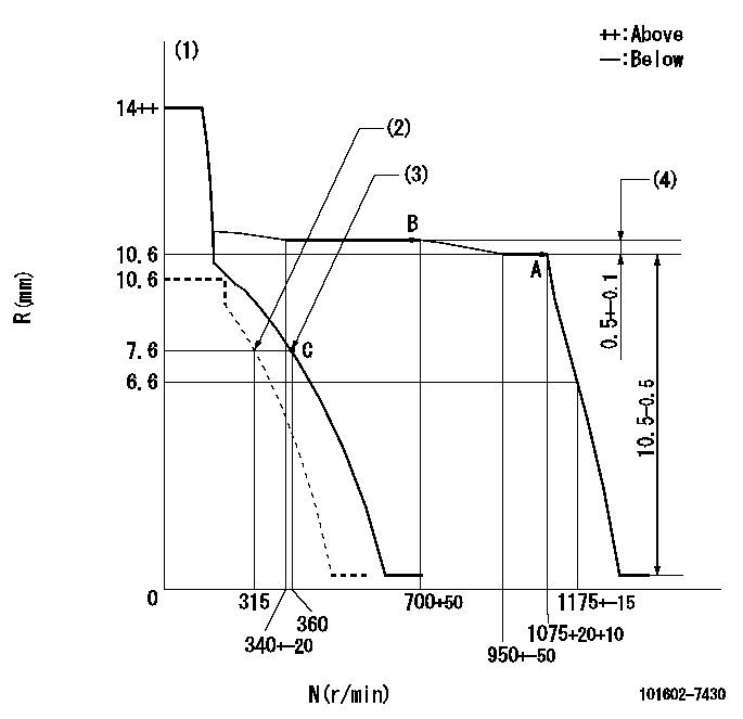
N:Pump speed
R:Rack position (mm)
(1)Target notch: K
(2)Set idle sub-spring
(3)Main spring setting
(4)Rack difference between N = N1 and N = N2
----------
K=6 N1=1075r/min N2=700r/min
----------
----------
K=6 N1=1075r/min N2=700r/min
----------
Speed control lever angle

F:Full speed
I:Idle
(1)Stopper bolt setting
----------
----------
a=(5deg)+-5deg b=(20deg)+-5deg
----------
----------
a=(5deg)+-5deg b=(20deg)+-5deg
Stop lever angle

N:Pump normal
S:Stop the pump.
----------
----------
a=12deg+-5deg b=46deg+-5deg
----------
----------
a=12deg+-5deg b=46deg+-5deg
Timing setting

(1)Pump vertical direction
(2)Position of flywheel's threaded hole at No 1 cylinder's beginning of injection
(3)B.T.D.C.: aa
(4)-
----------
aa=15deg
----------
a=(60deg)
----------
aa=15deg
----------
a=(60deg)
Information:
1. Exploded viewsIn the exploded views, the component parts are separated but so arranged to show their relationship to the whole. Index numbering is used to identify the parts and to indicate a sequence in which the parts are to be removed for disassembly, or they are to be installed for assembly. 2. SymbolsThe following symbols are used in this manual to emphasize important and critical instructions:
Indicates a condition that is essential to highlight.
Indicates a condition that can cause engine damage.
Indicates a condition that can cause personal injury or death.3. Definition of locational termsThe fan end is "front" and the flywheel end is "rear". The words "left" and "right" are as these directions would appear from the flywheel end.4. Dimensional or specification termsNominal size...Is the named size which has no specified limits of accuracy.Standard...Is the dimension of a part to be attained at the time of assembly, or the standard performance.Limit...Is the maximum or minimum permissible limit beyond which a part must be repaired or replaced.5. Tightening torquesTighten bolts, nuts, etc. in a wet condition (apply oil to threads) when specified as [WET]. Tighten them in a dry condition unless so specified. Use the general torques unless otherwise specified.MODEL IDENTIFICATION AND SERIAL NUMBER LOCATION
1. Model identification location(a) The model identification is embossed on the right side of the cylinder block, near the fuel injection pump mount.(b) The model identifications and displacements of the engines in current production are as listed below:
Model identification location(c) A scheme of coding used for identifying the engines in current production is as follows:
Example: Coded designation2. Serial Number LocationThe serial number is punched on the cylinder block, near the fuel injection pump mount.
Serial number locationCOMPONENT LOCATION
S3L/S3L2 S4L/S4L2SPECIFICATIONS
PERFORMANCE CURVES (ONE-HOUR RATING, WITH FAN)
PRIME POWER OUTPUT CHART