Information injection-pump assembly
BOSCH
9 400 611 894
9400611894
ZEXEL
101602-7340
1016027340
ISUZU
1156026700
1156026700
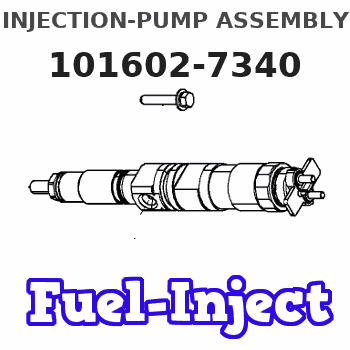
Rating:
Service parts 101602-7340 INJECTION-PUMP ASSEMBLY:
1.
_
5.
AUTOM. ADVANCE MECHANIS
6.
COUPLING PLATE
8.
_
9.
_
11.
Nozzle and Holder
1-15300-247-1
12.
Open Pre:MPa(Kqf/cm2)
18.1{185}
15.
NOZZLE SET
Include in #1:
101602-7340
as INJECTION-PUMP ASSEMBLY
Include in #2:
104749-6332
as _
Cross reference number
BOSCH
9 400 611 894
9400611894
ZEXEL
101602-7340
1016027340
ISUZU
1156026700
1156026700
Zexel num
Bosch num
Firm num
Name
101602-7340
9 400 611 894
1156026700 ISUZU
INJECTION-PUMP ASSEMBLY
6BG1-T K 14BE INJECTION PUMP ASSY PE6A PE
6BG1-T K 14BE INJECTION PUMP ASSY PE6A PE
Calibration Data:
Adjustment conditions
Test oil
1404 Test oil ISO4113 or {SAEJ967d}
1404 Test oil ISO4113 or {SAEJ967d}
Test oil temperature
degC
40
40
45
Nozzle and nozzle holder
105780-8140
Bosch type code
EF8511/9A
Nozzle
105780-0000
Bosch type code
DN12SD12T
Nozzle holder
105780-2080
Bosch type code
EF8511/9
Opening pressure
MPa
17.2
Opening pressure
kgf/cm2
175
Injection pipe
Outer diameter - inner diameter - length (mm) mm 6-2-600
Outer diameter - inner diameter - length (mm) mm 6-2-600
Overflow valve
131424-4920
Overflow valve opening pressure
kPa
127
107
147
Overflow valve opening pressure
kgf/cm2
1.3
1.1
1.5
Tester oil delivery pressure
kPa
157
157
157
Tester oil delivery pressure
kgf/cm2
1.6
1.6
1.6
Direction of rotation (viewed from drive side)
Right R
Right R
Injection timing adjustment
Direction of rotation (viewed from drive side)
Right R
Right R
Injection order
1-5-3-6-
2-4
Pre-stroke
mm
3.2
3.15
3.25
Beginning of injection position
Drive side NO.1
Drive side NO.1
Difference between angles 1
Cal 1-5 deg. 60 59.5 60.5
Cal 1-5 deg. 60 59.5 60.5
Difference between angles 2
Cal 1-3 deg. 120 119.5 120.5
Cal 1-3 deg. 120 119.5 120.5
Difference between angles 3
Cal 1-6 deg. 180 179.5 180.5
Cal 1-6 deg. 180 179.5 180.5
Difference between angles 4
Cyl.1-2 deg. 240 239.5 240.5
Cyl.1-2 deg. 240 239.5 240.5
Difference between angles 5
Cal 1-4 deg. 300 299.5 300.5
Cal 1-4 deg. 300 299.5 300.5
Injection quantity adjustment
Adjusting point
A
Rack position
7.4
Pump speed
r/min
900
900
900
Average injection quantity
mm3/st.
57
55.5
58.5
Max. variation between cylinders
%
0
-2.5
2.5
Basic
*
Fixing the rack
*
Injection quantity adjustment_02
Adjusting point
C
Rack position
5.6+-0.5
Pump speed
r/min
400
400
400
Average injection quantity
mm3/st.
9.3
8
10.6
Max. variation between cylinders
%
0
-14
14
Fixing the rack
*
Test data Ex:
Governor adjustment
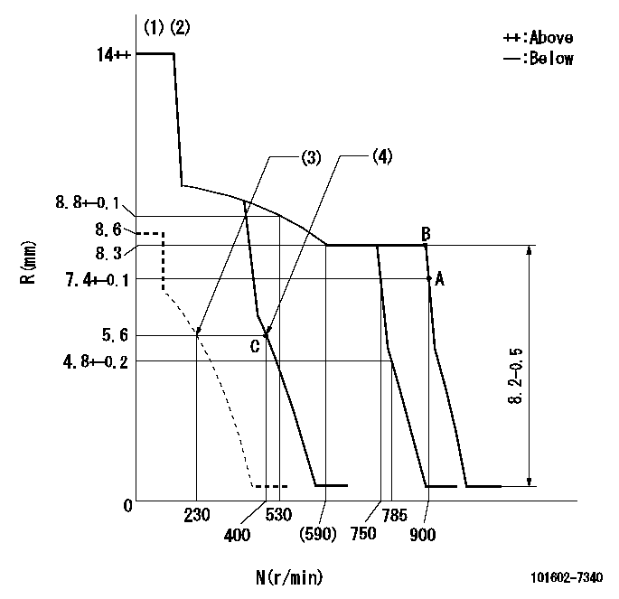
N:Pump speed
R:Rack position (mm)
(1)Target notch: K
(2)Tolerance for racks not indicated: +-0.05mm.
(3)Set idle sub-spring
(4)Main spring setting
----------
K=9+-1
----------
----------
K=9+-1
----------
Speed control lever angle
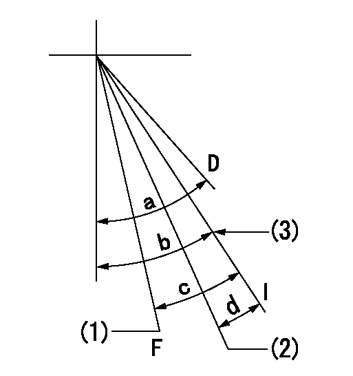
F:Full speed
I:Idle
D:Dead point
(1)Set the pump speed at aa. (At delivery)
(2)Pump speed = bb
(3)Stopper bolt setting
----------
aa=900r/min bb=750r/min
----------
a=20deg+-3deg b=18deg+-1deg c=16deg+-5deg d=12deg+-5deg
----------
aa=900r/min bb=750r/min
----------
a=20deg+-3deg b=18deg+-1deg c=16deg+-5deg d=12deg+-5deg
Stop lever angle

N:Pump normal
S:Stop the pump.
(1)Normal
----------
----------
a=2.5deg+-5deg b=46deg+-5deg
----------
----------
a=2.5deg+-5deg b=46deg+-5deg
0000001501 LEVER

1. Variable lever adjustment
(1)Fix lever (B) in the idle position using bolts (C) and (D).
(2)Temporarily fix the lever (A) in the center of the elongated hole.
(3)Set the dead point position temporarily and measure the lever angle.
(4)Fix the lever (A) at the idle lever angle position using the bolt (E).
(5)Lock using bolt (G).
(6)After completing idle adjustment, loosen the full side stopper bolt (D).
(7)Move the lever (A) in the full speed direction.
(8)Fix bolt (D) at full speed position.
(9)Finally, measure the lever angle and set the idle stopper bolt (C) stop position.
----------
----------
----------
----------
Timing setting
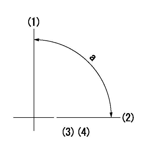
(1)Pump vertical direction
(2)Position of gear mark 'CC' at No 1 cylinder's beginning of injection
(3)B.T.D.C.: aa
(4)-
----------
aa=17deg
----------
a=(90deg)
----------
aa=17deg
----------
a=(90deg)
Information:
3-164D, 3-179D, 4-219D, 4-239D, 4-239T, 6-329D, 6-359D, Or 6-359T Engine
Removal
Fig. 1-Oil Cooler LinesDisconnect coolant lines (1, Fig. 1).Remove oil filter (2).
Fig. 2-Oil Cooler NippleUnscrew oil cooler nipple (Fig. 2) and lift oil cooler off of cylinder block.Remove four sided packing from bottom of oil cooler.Repair
Pressure check the coolant side of the oil cooler using 15 psi (103 kPa) (1 bar) maximum air pressure.Remove oil cooler bypass valve by driving it out the bottom of the oil cooler from the top side.
Fig. 3-Oil Cooler Bypass Valve and SpringInspect bypass valve and spring (Fig. 3) for damage and replace as necessary.Installation
Fig. 4-Four Sided PackingInstall new four sided packing (Fig. 4) on bottom of oil cooler.Position oil cooler on engine and install oil cooler nipple.
Fig. 5-Oil Cooler NippleOil cooler nipple torque (Fig. 5) ... 20 to 25 lb-ft(27 to 34 N m) (3.0 to 3.5 kg-m)Connect coolant hoses to oil cooler and install new oil filter (Group 0407).4-276D, 4-276T, 6-414D Or 6414T Engine
Removal
Fig. 6-Oil Cooler Assembly RemovalDisconnect coolant lines (1, Fig. 6) and remove oil filter (2).Remove oil cooler assembly attaching cap screws (3).Remove oil filter housing (4) from oil cooler.Repair
Remove top and bottom covers.
Fig. 7-Remove Oil CoolerUsing a suitable driver, drive oil cooler out of housing from bottom side (Fig. 7).
Fig. 8-Remove Oil Cooler Relief ValveDrive oil cooler bypass valve out the bottom from the top using a pin punch against the top of the valve (Fig. 8).
Fig. 9-Oil CoolerInspect oil cooler for damage or build-up of foreign material and clean as needed.The oil cooler can be pressure checked with a maximum of 50 psi (345 kPa) (3 bar) air pressure.
Fig. 10-Oil Cooler Bypass Valve Spring LengthCheck oil cooler bypass valve spring length:Valve spring length (Fig. 10) ... 1.91 inch(48.5 mm)when compressed with ... 29.5 to 37.5 lb(131 to 167 N)
Fig. 11-Remove O-RingsRemove O-rings from housing at bottom of oil cooler bore.Remove all gasket residue from parts.Installation
Fig. 12-Install Oil Cooler Relief ValvePosition oil cooler relief valve spring (1, Fig. 12), valve (2), and valve seat (3) in bore in bottom of housing (4).
Fig. 13-Drive Oil Cooler Relief Valve SeatUsing a suitable driver (Fig. 13), drive the valve seat into the housing until the seat bottoms.
Fig. 14-O-Ring InstallationInstall new O-rings in housing at bottom of oil cooler bore, black O-ring in upper groove (A, Fig. 14) and red O-ring in lower groove (B).Using new gasket, install oil cooler in housing from top side, being careful not to shear O-rings.Using new gaskets, install top and bottom covers and oil filter housing.Position oil cooler assembly on engine and install cap screws.Connect oil cooler coolant lines and install a new oil filter.
Removal
Fig. 1-Oil Cooler LinesDisconnect coolant lines (1, Fig. 1).Remove oil filter (2).
Fig. 2-Oil Cooler NippleUnscrew oil cooler nipple (Fig. 2) and lift oil cooler off of cylinder block.Remove four sided packing from bottom of oil cooler.Repair
Pressure check the coolant side of the oil cooler using 15 psi (103 kPa) (1 bar) maximum air pressure.Remove oil cooler bypass valve by driving it out the bottom of the oil cooler from the top side.
Fig. 3-Oil Cooler Bypass Valve and SpringInspect bypass valve and spring (Fig. 3) for damage and replace as necessary.Installation
Fig. 4-Four Sided PackingInstall new four sided packing (Fig. 4) on bottom of oil cooler.Position oil cooler on engine and install oil cooler nipple.
Fig. 5-Oil Cooler NippleOil cooler nipple torque (Fig. 5) ... 20 to 25 lb-ft(27 to 34 N m) (3.0 to 3.5 kg-m)Connect coolant hoses to oil cooler and install new oil filter (Group 0407).4-276D, 4-276T, 6-414D Or 6414T Engine
Removal
Fig. 6-Oil Cooler Assembly RemovalDisconnect coolant lines (1, Fig. 6) and remove oil filter (2).Remove oil cooler assembly attaching cap screws (3).Remove oil filter housing (4) from oil cooler.Repair
Remove top and bottom covers.
Fig. 7-Remove Oil CoolerUsing a suitable driver, drive oil cooler out of housing from bottom side (Fig. 7).
Fig. 8-Remove Oil Cooler Relief ValveDrive oil cooler bypass valve out the bottom from the top using a pin punch against the top of the valve (Fig. 8).
Fig. 9-Oil CoolerInspect oil cooler for damage or build-up of foreign material and clean as needed.The oil cooler can be pressure checked with a maximum of 50 psi (345 kPa) (3 bar) air pressure.
Fig. 10-Oil Cooler Bypass Valve Spring LengthCheck oil cooler bypass valve spring length:Valve spring length (Fig. 10) ... 1.91 inch(48.5 mm)when compressed with ... 29.5 to 37.5 lb(131 to 167 N)
Fig. 11-Remove O-RingsRemove O-rings from housing at bottom of oil cooler bore.Remove all gasket residue from parts.Installation
Fig. 12-Install Oil Cooler Relief ValvePosition oil cooler relief valve spring (1, Fig. 12), valve (2), and valve seat (3) in bore in bottom of housing (4).
Fig. 13-Drive Oil Cooler Relief Valve SeatUsing a suitable driver (Fig. 13), drive the valve seat into the housing until the seat bottoms.
Fig. 14-O-Ring InstallationInstall new O-rings in housing at bottom of oil cooler bore, black O-ring in upper groove (A, Fig. 14) and red O-ring in lower groove (B).Using new gasket, install oil cooler in housing from top side, being careful not to shear O-rings.Using new gaskets, install top and bottom covers and oil filter housing.Position oil cooler assembly on engine and install cap screws.Connect oil cooler coolant lines and install a new oil filter.
Have questions with 101602-7340?
Group cross 101602-7340 ZEXEL
Isuzu
101602-7340
9 400 611 894
1156026700
INJECTION-PUMP ASSEMBLY
6BG1-T
6BG1-T
