Information injection-pump assembly
ZEXEL
101602-7320
1016027320
ISUZU
1156026320
1156026320
Rating:
Service parts 101602-7320 INJECTION-PUMP ASSEMBLY:
1.
_
5.
AUTOM. ADVANCE MECHANIS
8.
_
9.
_
11.
Nozzle and Holder
5-15300-103-2
12.
Open Pre:MPa(Kqf/cm2)
14.7{150}
15.
NOZZLE SET
Cross reference number
ZEXEL
101602-7320
1016027320
ISUZU
1156026320
1156026320
Zexel num
Bosch num
Firm num
Name
Calibration Data:
Adjustment conditions
Test oil
1404 Test oil ISO4113 or {SAEJ967d}
1404 Test oil ISO4113 or {SAEJ967d}
Test oil temperature
degC
40
40
45
Nozzle and nozzle holder
105780-8140
Bosch type code
EF8511/9A
Nozzle
105780-0000
Bosch type code
DN12SD12T
Nozzle holder
105780-2080
Bosch type code
EF8511/9
Opening pressure
MPa
17.2
Opening pressure
kgf/cm2
175
Injection pipe
Outer diameter - inner diameter - length (mm) mm 6-2-600
Outer diameter - inner diameter - length (mm) mm 6-2-600
Tester oil delivery pressure
kPa
157
157
157
Tester oil delivery pressure
kgf/cm2
1.6
1.6
1.6
Direction of rotation (viewed from drive side)
Right R
Right R
Injection timing adjustment
Direction of rotation (viewed from drive side)
Right R
Right R
Injection order
1-5-3-6-
2-4
Pre-stroke
mm
3.6
3.55
3.65
Beginning of injection position
Drive side NO.1
Drive side NO.1
Difference between angles 1
Cal 1-5 deg. 60 59.5 60.5
Cal 1-5 deg. 60 59.5 60.5
Difference between angles 2
Cal 1-3 deg. 120 119.5 120.5
Cal 1-3 deg. 120 119.5 120.5
Difference between angles 3
Cal 1-6 deg. 180 179.5 180.5
Cal 1-6 deg. 180 179.5 180.5
Difference between angles 4
Cyl.1-2 deg. 240 239.5 240.5
Cyl.1-2 deg. 240 239.5 240.5
Difference between angles 5
Cal 1-4 deg. 300 299.5 300.5
Cal 1-4 deg. 300 299.5 300.5
Injection quantity adjustment
Adjusting point
A
Rack position
7.3
Pump speed
r/min
800
800
800
Average injection quantity
mm3/st.
63.8
62.8
64.8
Max. variation between cylinders
%
0
-2
2
Basic
*
Fixing the lever
*
Injection quantity adjustment_02
Adjusting point
-
Rack position
4.5+-0.5
Pump speed
r/min
350
350
350
Average injection quantity
mm3/st.
9.4
8.1
10.7
Max. variation between cylinders
%
0
-14
14
Fixing the rack
*
Remarks
Adjust only variation between cylinders; adjust governor according to governor specifications.
Adjust only variation between cylinders; adjust governor according to governor specifications.
Test data Ex:
Governor adjustment
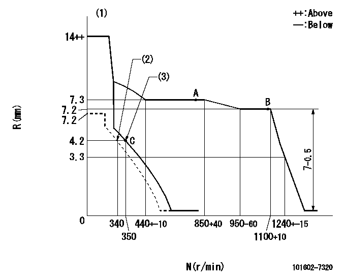
N:Pump speed
R:Rack position (mm)
(1)Target notch: K
(2)Set idle sub-spring
(3)Main spring setting
----------
K=12
----------
----------
K=12
----------
Speed control lever angle
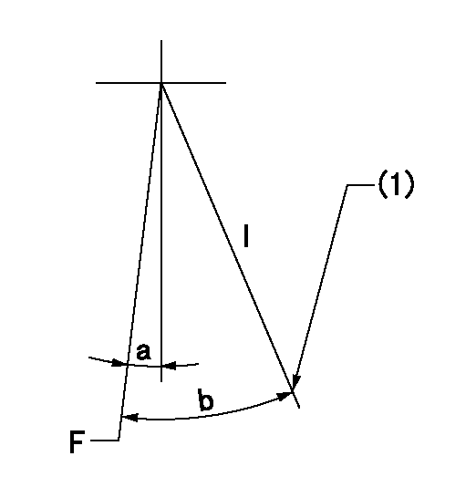
F:Full speed
I:Idle
(1)Stopper bolt setting
----------
----------
a=8deg+-5deg b=21deg+-5deg
----------
----------
a=8deg+-5deg b=21deg+-5deg
Stop lever angle
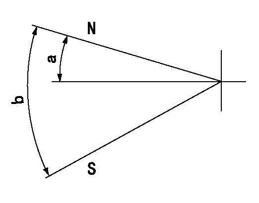
N:Pump normal
S:Stop the pump.
----------
----------
a=12deg+-5deg b=46deg+-5deg
----------
----------
a=12deg+-5deg b=46deg+-5deg
Timing setting

(1)Pump vertical direction
(2)Position of flywheel's threaded hole at No 1 cylinder's beginning of injection
(3)-
(4)-
----------
----------
a=(10deg)
----------
----------
a=(10deg)
Information:
Removal
Remove turbocharger (Group 0416) from turbocharged engines.Remove air inlet piping from non-turbocharged engines (Group 0520).Remove water manifolds or thermostat housing (Group 0418).Remove fuel filter (Group 0420).Remove exhaust manifold (Group 0410).Remove injection nozzles and injection lines (Group 0413).Remove rocker arm cover, rocker arm assembly, and pushrods (Group 0402).Remove cylinder head cap screws. Do not rotate crankshaft with cylinder head removed unless all cylinder liners are secured with short cap screws and large flat washers. IMPORTANT: Do not use screwdrivers or pry bars between cylinder block and cylinder head to loosen cylinder head.Lift cylinder head from cylinder block. If cylinder head sticks, use a soft hammer to tap the cylinder head.Remove any gasket residue remaining on cylinder head.Measure cylinder head deck to valve head distance with valve seated.
Fig. 1-Cylinder Head to Valve Head DistanceCylinder head to intake valve head distance (new) (1, Fig. 1) ... 0.037 0.007 inch(0.94 0.18 mm)Cylinder head to exhaust valve head distance (new) (2) ... 0.057 0.007 inch(1.45 0.18 mm)Disassembly
Fig. 2-Valve RemovalUsing a valve spring compressor, compress valve springs far enough to remove retainer locks.Release spring tension and remove valve spring cap (or rotator, if so equipped) and valve spring. Mark each part so that it can be reassembled in the same position it was removed from.Remove valves, marking them for reassembly.Repair
Fig. 3-Cylinder Head FlatnessMeasure cylinder head flatness (Fig. 3).Cylinder head flatness (maximum warp) ... 0.002 inch(0.05 mm)
Fig. 4-Cylinder Head ThicknessMeasure cylinder head thickness (Fig. 4), to see if cylinder head can be resurfaced.New cylinder head thickness ... 4.134 0.005 inch(105.00 0.13 mm)Minimum cylinder head thickness ... 4.104 inch(104.24)If cylinder head thickness is less than the minimum allowable thickness, do not resurface it. Install a new cylinder head.If cylinder head is thick enough to be resurfaced, remove only enough material to remove damage. Do not resurface cylinder head if its thickness will be less than the minimum allowable after resurfacing.
Fig. 5-Valve Face AngleIf necessary to resurface valve face, grind valve face at following angle (Fig. 5):
Fig. 6-Valve Seat AngleIf necessary to resurface valve seat, grind valve seat at following angle (Fig. 6):
Fig. 7-Valve Seat WidthWhen resurfacing valve seats, the valve seat width must be maintained (Fig. 7).
Fig. 8-Valve Seat Run-OutWhen resurfacing valve seats, the valve seat run-out must be maintained (Fig. 8).Valve seat run-out (maximum) ... 0.002 inch(0.05 mm)
Fig. 9-JDE-77 or JDE-87 Valve Seat PullerUse JDE-77A Valve Seat Puller to remove intake valve seat inserts or JDE-87 Valve Seat Puller to remove exhaust valve seat inserts if they must be replaced on 4276D, 6414D, or 6414T engine.Use JDE41296 Valve Seat Puller to remove valve seat inserts if they must be replaced on 4239D, 4239T, 6359D, or 6359T engine.
Fig. 10-JDE-7 Driver and JDE-86 or JD-287 Valve Seat InstallerUse JDE-7 Driver (1, Fig. 10) with JDE-86 valve seat installer (2) (for exhaust) and JD-287 valve seat installer (2) (for intake) to install valve seat inserts. Chill the valve seat installer and valve seat insert to -20°F
