Information injection-pump assembly
BOSCH
9 400 614 848
9400614848
ZEXEL
101602-4742
1016024742
ISUZU
1156021542
1156021542
Rating:
Service parts 101602-4742 INJECTION-PUMP ASSEMBLY:
1.
_
5.
AUTOM. ADVANCE MECHANIS
6.
COUPLING PLATE
8.
_
9.
_
11.
Nozzle and Holder
1-15300-161-0
12.
Open Pre:MPa(Kqf/cm2)
22.1(225)
15.
NOZZLE SET
Include in #1:
101602-4742
as INJECTION-PUMP ASSEMBLY
Include in #2:
104749-1480
as _
Cross reference number
BOSCH
9 400 614 848
9400614848
ZEXEL
101602-4742
1016024742
ISUZU
1156021542
1156021542
Zexel num
Bosch num
Firm num
Name
9 400 614 848
1156021542 ISUZU
INJECTION-PUMP ASSEMBLY
6SA1T * K 14BF PE6AD PE
6SA1T * K 14BF PE6AD PE
Calibration Data:
Adjustment conditions
Test oil
1404 Test oil ISO4113 or {SAEJ967d}
1404 Test oil ISO4113 or {SAEJ967d}
Test oil temperature
degC
40
40
45
Nozzle and nozzle holder
105780-8140
Bosch type code
EF8511/9A
Nozzle
105780-0000
Bosch type code
DN12SD12T
Nozzle holder
105780-2080
Bosch type code
EF8511/9
Opening pressure
MPa
17.2
Opening pressure
kgf/cm2
175
Injection pipe
Outer diameter - inner diameter - length (mm) mm 6-2-600
Outer diameter - inner diameter - length (mm) mm 6-2-600
Overflow valve opening pressure
kPa
157
123
191
Overflow valve opening pressure
kgf/cm2
1.6
1.25
1.95
Tester oil delivery pressure
kPa
157
157
157
Tester oil delivery pressure
kgf/cm2
1.6
1.6
1.6
Direction of rotation (viewed from drive side)
Left L
Left L
Injection timing adjustment
Direction of rotation (viewed from drive side)
Left L
Left L
Injection order
1-5-3-6-
2-4
Pre-stroke
mm
4.7
4.65
4.75
Beginning of injection position
Governor side NO.1
Governor side NO.1
Difference between angles 1
Cal 1-5 deg. 60 59.5 60.5
Cal 1-5 deg. 60 59.5 60.5
Difference between angles 2
Cal 1-3 deg. 120 119.5 120.5
Cal 1-3 deg. 120 119.5 120.5
Difference between angles 3
Cal 1-6 deg. 180 179.5 180.5
Cal 1-6 deg. 180 179.5 180.5
Difference between angles 4
Cyl.1-2 deg. 240 239.5 240.5
Cyl.1-2 deg. 240 239.5 240.5
Difference between angles 5
Cal 1-4 deg. 300 299.5 300.5
Cal 1-4 deg. 300 299.5 300.5
Injection quantity adjustment
Adjusting point
A
Rack position
10.3
Pump speed
r/min
1100
1100
1100
Average injection quantity
mm3/st.
123.6
122.6
124.6
Max. variation between cylinders
%
0
-2.5
2.5
Basic
*
Fixing the lever
*
Injection quantity adjustment_02
Adjusting point
B
Rack position
5.6+-0.5
Pump speed
r/min
350
350
350
Average injection quantity
mm3/st.
9
7
11
Max. variation between cylinders
%
0
-14
14
Fixing the rack
*
Test data Ex:
Governor adjustment
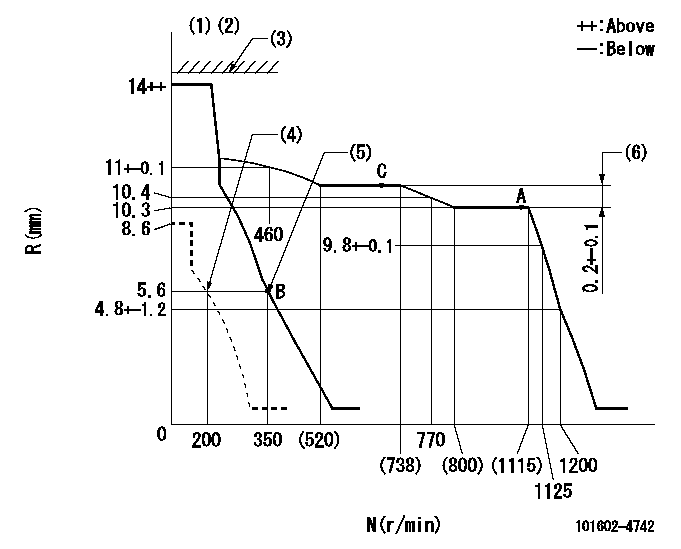
N:Pump speed
R:Rack position (mm)
(1)Target notch: K
(2)Tolerance for racks not indicated: +-0.05mm.
(3)RACK LIMIT not operating.
(4)Set idle sub-spring
(5)Main spring setting
(6)Rack difference between N = N1 and N = N2
----------
K=14 N1=1100r/min N2=700r/min
----------
----------
K=14 N1=1100r/min N2=700r/min
----------
Speed control lever angle
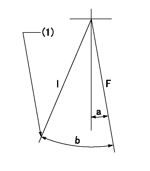
F:Full speed
I:Idle
(1)Stopper bolt setting
----------
----------
a=10deg+-5deg b=25deg+-5deg
----------
----------
a=10deg+-5deg b=25deg+-5deg
Stop lever angle
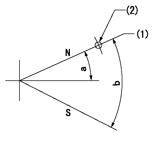
N:Pump normal
S:Stop the pump.
(1)Normal
(2)Use the hole at R = aa
----------
aa=60mm
----------
a=19deg+-5deg b=53deg+-5deg
----------
aa=60mm
----------
a=19deg+-5deg b=53deg+-5deg
Timing setting

(1)Pump vertical direction
(2)Position of coupling's threaded hole at No 1 cylinder's beginning of injection
(3)B.T.D.C.: aa
(4)-
----------
aa=20deg
----------
a=(40deg)
----------
aa=20deg
----------
a=(40deg)
Information:
Operation
At all speeds the rotor blades are kept in contact with the bore of the body by centrifugal force, assisted by the hydraulic action of the oil beneath the blades. When the rotor turns, the spaces between the blades vary because of the eccentric mounting of the rotor in the exhauster body. As a blade passes the inlet port, the space between it and the following blade is increasing and air is drawn from the vacuum reservoir. This air is then compressed and expelled, with the lubricating oil, through the outlet port to the engine timing case.Periodic Inspections and Preventive Maintenance
Every 5,000 miles (7,500 km) or 250 Hours
Check the vacuum lines and fittings. (Vacuum leakage may occur through the line, or reservoir mounted non-return valve if the valve seat is dirty or pitted). Examine the exhauster for evidence of oil leakage, particularly at end cover joints, and at shaft oil seal.Check the oil supply line for leaks at fittings and connections.Check the mounting and end cover nuts and bolts for tightness.Every 60,000 Miles (90,000 km) or 2,500 Hours
Remove and dismantle exhauster, thoroughly clean all parts and inspect for wear and damage. Repair or replace the exhauster with a Factory Replacement Unit.Removal
Disconnect oil and vacuum pipes at the exhauster and plug ends to prevent the entry of foreign matter.
Q2 1. Distance Piece2. ExhausterUndo the four nuts that secure the exhauster to the timing case, and withdraw the unit complete with its driving gear, from the studs (Fig. Q.2).Dismantling
Remove the two half-round thrust plates which locate the drive gear on the front of exhauster shaft.Remove drive gear.Mark the end covers in relation to the body to correct location on re-assembly.Unscrew four setscrews and remove rear end cover with rubber sealing ring.Mark the blades in relation to the rotor.Withdraw the rotor and fibre blades from the body.Unscrew four socket headed screws, and remove drive end cover, with joint or rubber ring.Remove rear end cover circlip, blanking disc, and rubber oil seal ring, if fitted. Further dismantling of the rotor assembly need be undertaken only if, after inspection, it is found necessary to renew the bearing or shaft collar.Cleaning and Inspection Cleaning
Wash the roller bearing, where fitted, in thin flushing oil or white spirit and blow dry with compressed air. Spinning the bearing with compressed air should be avoided, otherwise damage to the rollers and race will occur.Wash the remaining components in cleaning solvent, and clear the rotor and drive end cover oilways with compressed air.Inspection of Parts
Examine the roller bearings, where fitted, for discolouration, wear, pitting and cracked races. Rotate slowly to examine for roughness. To renew, see "Overhaul" Section. Premature failure may have been caused by shortage of oil.Examine plain bearing(s) for excessive wear. To renew, see "Overhaul" Section.Inspect rotor and shaft for cracks and damage, and the shaft seal collar for wear. To renew collar, see "Overhaul" Section.Check fit of blades in rotor slots, replace any worn or damaged blades.Examine the seal(s) carefully to see that the sealing edge