Information injection-pump assembly
ZEXEL
101602-4740
1016024740
ISUZU
1156021540
1156021540

Rating:
Cross reference number
ZEXEL
101602-4740
1016024740
ISUZU
1156021540
1156021540
Zexel num
Bosch num
Firm num
Name
Calibration Data:
Adjustment conditions
Test oil
1404 Test oil ISO4113 or {SAEJ967d}
1404 Test oil ISO4113 or {SAEJ967d}
Test oil temperature
degC
40
40
45
Nozzle and nozzle holder
105780-8140
Bosch type code
EF8511/9A
Nozzle
105780-0000
Bosch type code
DN12SD12T
Nozzle holder
105780-2080
Bosch type code
EF8511/9
Opening pressure
MPa
17.2
Opening pressure
kgf/cm2
175
Injection pipe
Outer diameter - inner diameter - length (mm) mm 6-2-600
Outer diameter - inner diameter - length (mm) mm 6-2-600
Overflow valve opening pressure
kPa
157
123
191
Overflow valve opening pressure
kgf/cm2
1.6
1.25
1.95
Tester oil delivery pressure
kPa
157
157
157
Tester oil delivery pressure
kgf/cm2
1.6
1.6
1.6
Direction of rotation (viewed from drive side)
Left L
Left L
Injection timing adjustment
Direction of rotation (viewed from drive side)
Left L
Left L
Injection order
1-5-3-6-
2-4
Pre-stroke
mm
4.7
4.65
4.75
Beginning of injection position
Governor side NO.1
Governor side NO.1
Difference between angles 1
Cal 1-5 deg. 60 59.5 60.5
Cal 1-5 deg. 60 59.5 60.5
Difference between angles 2
Cal 1-3 deg. 120 119.5 120.5
Cal 1-3 deg. 120 119.5 120.5
Difference between angles 3
Cal 1-6 deg. 180 179.5 180.5
Cal 1-6 deg. 180 179.5 180.5
Difference between angles 4
Cyl.1-2 deg. 240 239.5 240.5
Cyl.1-2 deg. 240 239.5 240.5
Difference between angles 5
Cal 1-4 deg. 300 299.5 300.5
Cal 1-4 deg. 300 299.5 300.5
Injection quantity adjustment
Adjusting point
A
Rack position
10.3
Pump speed
r/min
1100
1100
1100
Average injection quantity
mm3/st.
123.6
122.6
124.6
Max. variation between cylinders
%
0
-2.5
2.5
Basic
*
Fixing the lever
*
Injection quantity adjustment_02
Adjusting point
B
Rack position
5.6+-0.5
Pump speed
r/min
350
350
350
Average injection quantity
mm3/st.
9
7
11
Max. variation between cylinders
%
0
-14
14
Fixing the rack
*
Test data Ex:
Governor adjustment
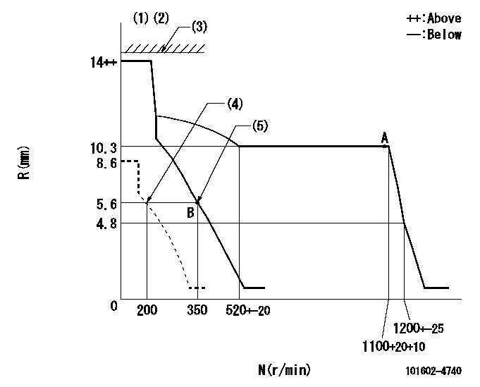
N:Pump speed
R:Rack position (mm)
(1)Target notch: K
(2)The torque control spring does not operate.
(3)RACK LIMIT not operating.
(4)Set idle sub-spring
(5)Main spring setting
----------
K=12
----------
----------
K=12
----------
Speed control lever angle
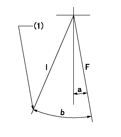
F:Full speed
I:Idle
(1)Stopper bolt setting
----------
----------
a=10deg+-5deg b=25deg+-5deg
----------
----------
a=10deg+-5deg b=25deg+-5deg
Stop lever angle
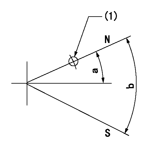
N:Pump normal
S:Stop the pump.
(1)Use the hole at R = aa
----------
aa=60mm
----------
a=19deg+-5deg b=53deg+-5deg
----------
aa=60mm
----------
a=19deg+-5deg b=53deg+-5deg
Timing setting

(1)Pump vertical direction
(2)Position of coupling's threaded hole at No 1 cylinder's beginning of injection
(3)B.T.D.C.: aa
(4)-
----------
aa=20deg
----------
a=(40deg)
----------
aa=20deg
----------
a=(40deg)
Information:
* Check that there is continuity between each stator lead.* If there is no continuity, the lead has broken.(2) Continuity between each lead wires and the core * Check that there is no continuity between lead wires and the core.* If there is continuity, the lead wire has short-circuited. Inspection: Brush* If the length of the brush has reached wear limit, replace the brush. Inspection: Rectifier* Check the function of diodes within rectifier properly. If any fault is found, replace the rectifier. If resistance is infinite in both cases, the diode is open.If resistance is close to 0 ohms in both cases, the diode is shorted.A, B, C: Lead connecting area of stator coilD, F: Heat sink areaE: Regulator connecting area* Inspection should be conducted twice, changed over the positive probe and the negative probe of the tester.* When inspecting using a tester, the current flowing through the rectifier is smaller than usual. Therefore, an incorrect resistance value may be indicated on the tester. Additionally, incorrect indications become larger as the range of the tester gets smaller. Set the tester to the largest possible scale. Assembly Procedure Assembly: Regulator and brush holder* To install the regulator and brush holder, follow the disassembly sequence in reverse. (See " Disassembly: Regulator and brush holder".) Assembly: Brush * Install brush on regulator and brush holder in the direction as illustrated.* After installation, solder the lead wire of brush on the regulator and brush holder. Thereafter, fit the cover as it was. Assembly: Stator* To install the stator, follow the disassembly sequence in reverse. (See " Disassembly: Stator".) Assembly: Rotor and rear bracket * If brush protrudes from regulator and brush holder, rotor cannot be installed onto the rear bracket. In this case, do the following:* Push brush into regulator and brush holder.* Insert pin into rear bracket from the rear to hold brush.* After assembly, remove pin gently.#950 Inspection Of Alternator
Performance Test* The general inspection is only a simplified check. use a test bench for accurate checking.* Connect the meters to the alternator as shown.
* To prevent possible injury, be sure to disconnect the negative terminal of
Performance Test* The general inspection is only a simplified check. use a test bench for accurate checking.* Connect the meters to the alternator as shown.
* To prevent possible injury, be sure to disconnect the negative terminal of