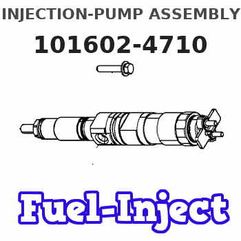
Information injection-pump assembly
ZEXEL
101602-4710
1016024710
ISUZU
1156021370
1156021370
Rating:
Service parts 101602-4710 INJECTION-PUMP ASSEMBLY:
1.
_
5.
AUTOM. ADVANCE MECHANIS
8.
_
9.
_
11.
Nozzle and Holder
1-15300-161-0
12.
Open Pre:MPa(Kqf/cm2)
22.1(225)
15.
NOZZLE SET
Include in #1:
101602-4710
as INJECTION-PUMP ASSEMBLY
Include in #2:
104749-1470
as _
Cross reference number
ZEXEL
101602-4710
1016024710
ISUZU
1156021370
1156021370
Zexel num
Bosch num
Firm num
Name
Calibration Data:
Adjustment conditions
Test oil
1404 Test oil ISO4113 or {SAEJ967d}
1404 Test oil ISO4113 or {SAEJ967d}
Test oil temperature
degC
40
40
45
Nozzle and nozzle holder
105780-8140
Bosch type code
EF8511/9A
Nozzle
105780-0000
Bosch type code
DN12SD12T
Nozzle holder
105780-2080
Bosch type code
EF8511/9
Opening pressure
MPa
17.2
Opening pressure
kgf/cm2
175
Injection pipe
Outer diameter - inner diameter - length (mm) mm 6-2-600
Outer diameter - inner diameter - length (mm) mm 6-2-600
Overflow valve opening pressure
kPa
157
123
191
Overflow valve opening pressure
kgf/cm2
1.6
1.25
1.95
Tester oil delivery pressure
kPa
157
157
157
Tester oil delivery pressure
kgf/cm2
1.6
1.6
1.6
Direction of rotation (viewed from drive side)
Left L
Left L
Injection timing adjustment
Direction of rotation (viewed from drive side)
Left L
Left L
Injection order
1-5-3-6-
2-4
Pre-stroke
mm
4.7
4.65
4.75
Beginning of injection position
Governor side NO.1
Governor side NO.1
Difference between angles 1
Cal 1-5 deg. 60 59.5 60.5
Cal 1-5 deg. 60 59.5 60.5
Difference between angles 2
Cal 1-3 deg. 120 119.5 120.5
Cal 1-3 deg. 120 119.5 120.5
Difference between angles 3
Cal 1-6 deg. 180 179.5 180.5
Cal 1-6 deg. 180 179.5 180.5
Difference between angles 4
Cyl.1-2 deg. 240 239.5 240.5
Cyl.1-2 deg. 240 239.5 240.5
Difference between angles 5
Cal 1-4 deg. 300 299.5 300.5
Cal 1-4 deg. 300 299.5 300.5
Injection quantity adjustment
Adjusting point
A
Rack position
9.2
Pump speed
r/min
1050
1050
1050
Average injection quantity
mm3/st.
101.4
100.4
102.4
Max. variation between cylinders
%
0
-2.5
2.5
Basic
*
Fixing the lever
*
Injection quantity adjustment_02
Adjusting point
B
Rack position
5.6+-0.5
Pump speed
r/min
350
350
350
Average injection quantity
mm3/st.
9
7
11
Max. variation between cylinders
%
0
-14
14
Fixing the rack
*
Test data Ex:
Governor adjustment
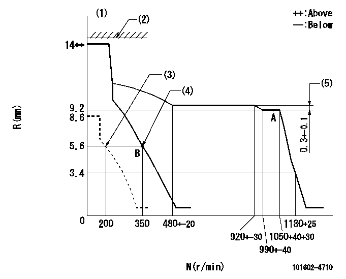
N:Pump speed
R:Rack position (mm)
(1)Target notch: K
(2)RACK LIMIT not operating.
(3)Set idle sub-spring
(4)Main spring setting
(5)Rack difference between N = N1 and N = N2
----------
K=12 N1=1050r/min N2=800r/min
----------
----------
K=12 N1=1050r/min N2=800r/min
----------
Speed control lever angle
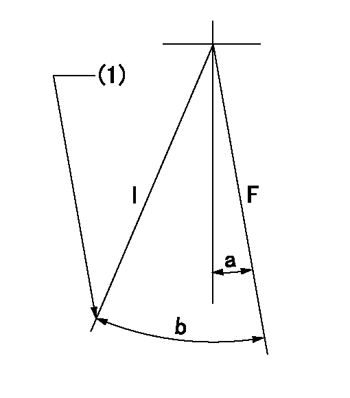
F:Full speed
I:Idle
(1)Stopper bolt setting
----------
----------
a=(9deg)+-5deg b=(23deg)+-5deg
----------
----------
a=(9deg)+-5deg b=(23deg)+-5deg
Stop lever angle

N:Pump normal
S:Stop the pump.
----------
----------
a=19deg+-5deg b=53deg+-5deg
----------
----------
a=19deg+-5deg b=53deg+-5deg
Timing setting

(1)Pump vertical direction
(2)Position of coupling's threaded hole at No 1 cylinder's beginning of injection
(3)B.T.D.C.: aa
(4)-
----------
aa=20deg
----------
a=(40deg)
----------
aa=20deg
----------
a=(40deg)
Information:
* For the frequency and timing of cleaning, refer to the relevant instruction manual. More frequent cleaning than necessary could damage the element or cause dust and foreign matter to be sucked into the engine.* Do not strike the element or hit it against another object to remove dust.* Do not blow compressed air against outside surfaces of the element.
Inspection Procedure Inspection: Outer Element* Shine some electric light inside the element.* Replace the element if thin spots or broken parts are evident in the filter paper, or if the packing at the top of the element is damaged. Also replace the element if the dust on the element is damp with oily smoke or soot, regardless of the replacement schedule. Inspection: Operation of dust indicator under specific negative pressure * Perform the following inspection and, if faulty, replace the dust indicator.* With no vacuum applied to the dust indicator, take measurement between the terminals 1 and 2. There should be no continuity.* Gradually apply vacuum to the dust indicator. Measure the vacuum when the continuity is made between the terminals 1 and 2.Turbocharger
Removal Sequence1 Turbocharger coupler2 Gasket3 Turbocharger insulator B4 Turbocharger insulator A5 Oil return pipe6 Gasket7 Eyebolt8 Oil pipe9 Turbocharger (See later sections.)10 Gasket*a: Exhaust manifoldX: Non-reusable parts Installation SequenceFollow the removal sequence in reverse.Tightening torque (Unit: N m {kgf m} Lubricant and/or sealant Installation Procedure Installation: Turbocharger* When installing the turbocharger, pour an appropriate amount of engine oil from the oil port so that each part operates smoothly.Turbocharger Disassembly Sequence1 Hose2 Actuator3 Coupling4 Turbine housing5 Snap ring6 Compressor cover7 O-ring8 Cartridge assemblyX: Non-resusable parts Assembly SequenceFollow the disassembly sequence in reverse.Service standards (Unit: mm) Tightening torque (Unit: N m {kgf m} Lubricant and/or sealant Work Before Removal Mating Marks* Draw a line across the coupling, turbine housing, compressor cover, and cartridge assembly. This line will serve as mating marks in the installation procedure. Removal Procedure Removal: Turbine housing
* Tap all around the end of the turbine housing with a rubber hammer or a similar tool, being careful not to damage the turbine housing.* Do not let the blades of the cartridge assembly hit the turbine housing, as they are easily bent.
Removal: Compressor Cover
* Tap all around the end of the turbine housing with a rubber hammer or a similar tool, being careful not damage the turbine housing.* Do not let the blades of the cartridge assembly hit the turbine housing, as they are easily bent.
Work after Disassembly Cleaning* Before cleaning the parts, carry out a visual inspection for any marks of burns or wear that may become difficult to find after the cleaning. If any defects are evident, replace the part(s).* Immerse the disassembled parts in an inflammable solvent (a 5 to 10 aqueous solution of Oil Clean from New Hope Co., Ltd.). Take out the parts from the solvent and dry them with compressed air. If there is any solid matter remaining on the parts, remove them with a plastic scraper or a bristle brush.
*