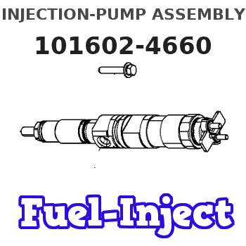
Information injection-pump assembly
ZEXEL
101602-4660
1016024660
ISUZU
1156021250
1156021250
Rating:
Service parts 101602-4660 INJECTION-PUMP ASSEMBLY:
1.
_
5.
AUTOM. ADVANCE MECHANIS
8.
_
9.
_
11.
Nozzle and Holder
1-15300-105-1
12.
Open Pre:MPa(Kqf/cm2)
18.1(185)

15.
NOZZLE SET
Include in #1:
101602-4660
as INJECTION-PUMP ASSEMBLY
Include in #2:
104748-1450
as _
Cross reference number
ZEXEL
101602-4660
1016024660
ISUZU
1156021250
1156021250
Zexel num
Bosch num
Firm num
Name
101602-4660
1156021250 ISUZU
INJECTION-PUMP ASSEMBLY
6BG1T * K
6BG1T * K
Calibration Data:
Adjustment conditions
Test oil
1404 Test oil ISO4113 or {SAEJ967d}
1404 Test oil ISO4113 or {SAEJ967d}
Test oil temperature
degC
40
40
45
Nozzle and nozzle holder
105780-8140
Bosch type code
EF8511/9A
Nozzle
105780-0000
Bosch type code
DN12SD12T
Nozzle holder
105780-2080
Bosch type code
EF8511/9
Opening pressure
MPa
17.2
Opening pressure
kgf/cm2
175
Injection pipe
Outer diameter - inner diameter - length (mm) mm 6-2-600
Outer diameter - inner diameter - length (mm) mm 6-2-600
Overflow valve opening pressure
kPa
127
107
147
Overflow valve opening pressure
kgf/cm2
1.3
1.1
1.5
Tester oil delivery pressure
kPa
157
157
157
Tester oil delivery pressure
kgf/cm2
1.6
1.6
1.6
Direction of rotation (viewed from drive side)
Right R
Right R
Injection timing adjustment
Direction of rotation (viewed from drive side)
Right R
Right R
Injection order
1-5-3-6-
2-4
Pre-stroke
mm
3.4
3.35
3.45
Beginning of injection position
Drive side NO.1
Drive side NO.1
Difference between angles 1
Cal 1-5 deg. 60 59.5 60.5
Cal 1-5 deg. 60 59.5 60.5
Difference between angles 2
Cal 1-3 deg. 120 119.5 120.5
Cal 1-3 deg. 120 119.5 120.5
Difference between angles 3
Cal 1-6 deg. 180 179.5 180.5
Cal 1-6 deg. 180 179.5 180.5
Difference between angles 4
Cyl.1-2 deg. 240 239.5 240.5
Cyl.1-2 deg. 240 239.5 240.5
Difference between angles 5
Cal 1-4 deg. 300 299.5 300.5
Cal 1-4 deg. 300 299.5 300.5
Injection quantity adjustment
Adjusting point
A
Rack position
8.3
Pump speed
r/min
1100
1100
1100
Average injection quantity
mm3/st.
78.1
76.6
79.6
Max. variation between cylinders
%
0
-2.5
2.5
Basic
*
Fixing the lever
*
Injection quantity adjustment_02
Adjusting point
B
Rack position
5+-0.5
Pump speed
r/min
325
325
325
Average injection quantity
mm3/st.
11
9.7
12.3
Max. variation between cylinders
%
0
-14
14
Fixing the rack
*
Test data Ex:
Governor adjustment
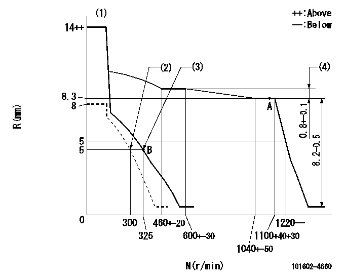
N:Pump speed
R:Rack position (mm)
(1)Target notch: K
(2)Set idle sub-spring
(3)Main spring setting
(4)Rack difference between N = N1 and N = N2
----------
K=14 N1=1100r/min N2=550r/min
----------
----------
K=14 N1=1100r/min N2=550r/min
----------
Speed control lever angle
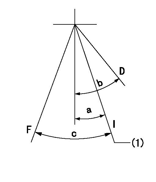
F:Full speed
I:Idle
D:Dead point
(1)Stopper bolt setting
----------
----------
a=16deg+-1deg b=20deg+-3deg c=21deg+-5deg
----------
----------
a=16deg+-1deg b=20deg+-3deg c=21deg+-5deg
Stop lever angle

N:Pump normal
S:Stop the pump.
----------
----------
a=12deg+-5deg b=46deg+-5deg
----------
----------
a=12deg+-5deg b=46deg+-5deg
0000001501 LEVER
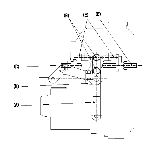
1. Variable lever adjustment
(1)Fix lever (B) in the idle position using bolts (C) and (D).
(2)Temporarily fix the lever (A) at the dead point and measure the lever angle .
(3)Fix the lever (A) at the idle lever angle position using the bolt (E).
(4)Lock using bolt (G).
(5)After completing idle adjustment, loosen the full side stopper bolt (D).
(6)Move the lever (A) in the full speed direction.
(7)Fix bolt (D) at full speed position.
(8)Finally, measure the lever angle and set the idle stopper bolt (C) stop position.
----------
----------
----------
----------
Timing setting

(1)Pump vertical direction
(2)Position of flywheel's threaded hole at No 1 cylinder's beginning of injection
(3)B.T.D.C.: aa
(4)-
----------
aa=15deg
----------
a=(10deg)
----------
aa=15deg
----------
a=(10deg)
Information:
Precautions for Electrical System
* Before working on the electrical system, disconnect the (-) battery cable to prevent short circuits.
* Make sure the electrical equipment is OFF before disconnecting or connecting battery cable. Semiconductor components may otherwise be damaged.
* Carefully handle sensors relays, and other items that are sensitive to shock and heat. * When applying a voltage to a part for inspection purposes, check that the (+) and (-) cables are connected properly then gradually increase the voltage from zero. Do not exceed the specified voltage. Remember that sensors do not necessarily operate on the battery voltage. * When separating connectors, grasp the connectors themselves rather than the harnesses. * To separate locking connectors, first push them in the direction of the arrows. To reconnect locking connectors, push them together until they click.* Before washing the parts, cover electrical parts to keep them dry. (Use plastic sheets or the like.) Keep water away from harness connectors and sensors and immediately wipe off any water that gets on them. Handling precautions for electric circuits
* Do not pierce wire insulation with test probes or alligator clips when performing electrical inspections. Doing so can, particularly with the chassis harness, hasten corrosion.
(1) Inspection of harnesses (1.1) Inspections with connectors fitted together* Waterproof connectors* Connect an inspection harness and connector. A between the connectors B of the circuit to be inspected. Perform the inspection by applying a test probe C to the connectors of the inspection harness. Do not insert the test probe C into the wire-entry sides of the waterproof connectors since this would damage their waterproof seals and lead to rust. * Non-waterproof connectors* Perform the inspection by inserting a test probe C into the wire-entry sides of the connectors. An extra-narrow probe is required for control unit connectors, which are smaller than other types of connector. Do not force a regular-size probe into control unit connectors since this would cause damage. (1.2) Inspections with connectors separated* Inspections on female terminals* Perform the inspection by carefully inserting a test probe into the terminals. Do not force the test probe into the terminals since this could deform them and cause poor connections. * Inspections on male terminals* Perform the inspection by applying test probes directly to the pins.
* Be careful not to short-circuit pins together with the test probes. With control unit connectors, short-circuiting of pins can cause damage to the control unit's internal circuitry.
* When using a multimeter to check continuity, do not allow the test probes to touch the wrong terminals. (2) Inspection of connectors (2.1) Visual inspection* Check that the connectors are fitted together securely. * Check whether wires have been separated from their terminals due to pulling of the harness. * Check that male and female terminals fit together tightly. * Check for defective connections caused by loose terminals, by rust on terminals, or by contamination of terminals by foreign substances. (2.2) Checking for loose terminals* If connector terminal retainers become damaged, male and female terminals may not
Have questions with 101602-4660?
Group cross 101602-4660 ZEXEL
Isuzu
101602-4660
1156021250
INJECTION-PUMP ASSEMBLY
6BG1T
6BG1T