Information injection-pump assembly
BOSCH
9 400 610 097
9400610097
ZEXEL
101602-4652
1016024652
ISUZU
1156021061
1156021061
Rating:
Service parts 101602-4652 INJECTION-PUMP ASSEMBLY:
1.
_
5.
AUTOM. ADVANCE MECHANIS
8.
_
9.
_
11.
Nozzle and Holder
1-15300-105-2
12.
Open Pre:MPa(Kqf/cm2)
18.1{185}

15.
NOZZLE SET
Include in #1:
101602-4652
as INJECTION-PUMP ASSEMBLY
Include in #2:
104748-1440
as _
Cross reference number
BOSCH
9 400 610 097
9400610097
ZEXEL
101602-4652
1016024652
ISUZU
1156021061
1156021061
Zexel num
Bosch num
Firm num
Name
101602-4652
9 400 610 097
1156021061 ISUZU
INJECTION-PUMP ASSEMBLY
6BD1T K 14BE INJECTION PUMP ASSY PE6A PE
6BD1T K 14BE INJECTION PUMP ASSY PE6A PE
Calibration Data:
Adjustment conditions
Test oil
1404 Test oil ISO4113 or {SAEJ967d}
1404 Test oil ISO4113 or {SAEJ967d}
Test oil temperature
degC
40
40
45
Nozzle and nozzle holder
105780-8140
Bosch type code
EF8511/9A
Nozzle
105780-0000
Bosch type code
DN12SD12T
Nozzle holder
105780-2080
Bosch type code
EF8511/9
Opening pressure
MPa
17.2
Opening pressure
kgf/cm2
175
Injection pipe
Outer diameter - inner diameter - length (mm) mm 6-2-600
Outer diameter - inner diameter - length (mm) mm 6-2-600
Overflow valve opening pressure
kPa
127
107
147
Overflow valve opening pressure
kgf/cm2
1.3
1.1
1.5
Tester oil delivery pressure
kPa
157
157
157
Tester oil delivery pressure
kgf/cm2
1.6
1.6
1.6
Direction of rotation (viewed from drive side)
Right R
Right R
Injection timing adjustment
Direction of rotation (viewed from drive side)
Right R
Right R
Injection order
1-5-3-6-
2-4
Pre-stroke
mm
3.4
3.35
3.45
Beginning of injection position
Drive side NO.1
Drive side NO.1
Difference between angles 1
Cal 1-5 deg. 60 59.5 60.5
Cal 1-5 deg. 60 59.5 60.5
Difference between angles 2
Cal 1-3 deg. 120 119.5 120.5
Cal 1-3 deg. 120 119.5 120.5
Difference between angles 3
Cal 1-6 deg. 180 179.5 180.5
Cal 1-6 deg. 180 179.5 180.5
Difference between angles 4
Cyl.1-2 deg. 240 239.5 240.5
Cyl.1-2 deg. 240 239.5 240.5
Difference between angles 5
Cal 1-4 deg. 300 299.5 300.5
Cal 1-4 deg. 300 299.5 300.5
Injection quantity adjustment
Adjusting point
A
Rack position
7.9
Pump speed
r/min
1100
1100
1100
Average injection quantity
mm3/st.
70.8
69.3
72.3
Max. variation between cylinders
%
0
-2.5
2.5
Basic
*
Fixing the lever
*
Boost pressure
kPa
26
26
Boost pressure
mmHg
195
195
Injection quantity adjustment_02
Adjusting point
B
Rack position
8.3
Pump speed
r/min
500
500
500
Average injection quantity
mm3/st.
53.8
51.8
55.8
Max. variation between cylinders
%
0
-4
4
Fixing the lever
*
Boost pressure
kPa
0
0
0
Boost pressure
mmHg
0
0
0
Injection quantity adjustment_03
Adjusting point
C
Rack position
5.8+-0.5
Pump speed
r/min
325
325
325
Average injection quantity
mm3/st.
14.5
13.2
15.8
Max. variation between cylinders
%
0
-14
14
Fixing the rack
*
Boost pressure
kPa
0
0
0
Boost pressure
mmHg
0
0
0
Boost compensator adjustment
Pump speed
r/min
520
520
520
Rack position
8.3
Boost pressure
kPa
11.3
6
16.6
Boost pressure
mmHg
85
45
125
Boost compensator adjustment_02
Pump speed
r/min
520
520
520
Rack position
8.8
Boost pressure
kPa
18
16.7
19.3
Boost pressure
mmHg
135
125
145
Test data Ex:
Governor adjustment
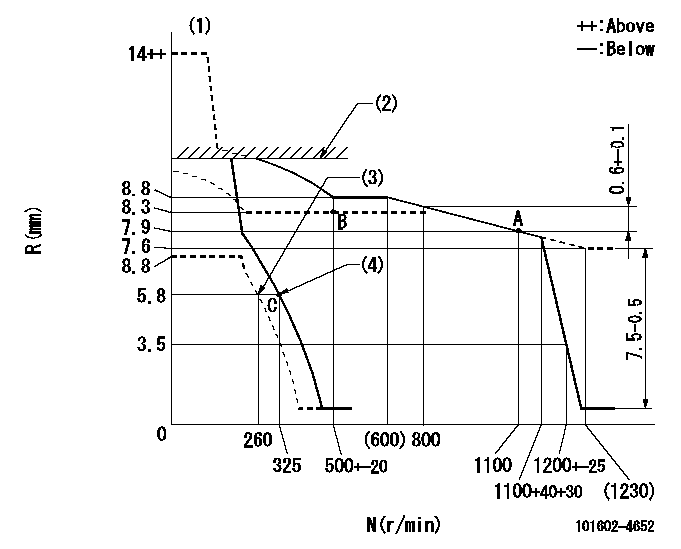
N:Pump speed
R:Rack position (mm)
(1)Target notch: K
(2)Boost compensator operation limit position: L1
(3)Set idle sub-spring
(4)Main spring setting
----------
K=5 L1=(10.5)mm
----------
----------
K=5 L1=(10.5)mm
----------
Speed control lever angle
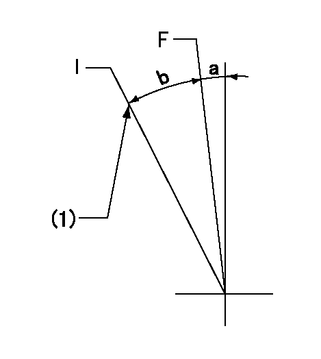
F:Full speed
I:Idle
(1)Stopper bolt setting
----------
----------
a=3deg+-5deg b=21deg+-5deg
----------
----------
a=3deg+-5deg b=21deg+-5deg
Stop lever angle

N:Pump normal
S:Stop the pump.
----------
----------
a=12deg+-5deg b=46deg+-5deg
----------
----------
a=12deg+-5deg b=46deg+-5deg
Timing setting

(1)Pump vertical direction
(2)Position of flywheel's threaded hole at No 1 cylinder's beginning of injection
(3)-
(4)-
----------
----------
a=(10deg)
----------
----------
a=(10deg)
Information:
(b) 4.248 Engines (4 Ring)
**Spring Loaded Conformable Scraper - above gudgeon pin.Internally Stepped Compression - third groove.*Internally Stepped Compression - second groove.Chrome Insert Barrel Faced Compression - top groove.When fitting sealed power rings, ensure that the ends of the spring loaded segment butt together and do not overlap.**Some earlier A4.248 engines had a sealed power scraper ring fitted in the 4th groove. *On some earlier A4.248 engines rated up to 2,000 rev/min, the second compression ring is plain cast iron.Some later engines, rated up to 2,000 rev/min, have internally stepped chrome faced rings in both 2nd and 3rd grooves.When fitting internally stepped compression rings, ensure that the step is towards the piston crown.When fitting the spring loaded conformable scraper ring, ensure that the latch pin enters both ends of the spring. With the ring gap diametrically opposite to the latch pin, position the oil control ring over spring correctly located in annular groove of ring, i.e., between the oil control ring and the bottom of the ring groove in the piston.(c) 4.248 Engines (3 Ring)
Chrome Faced Spring Loaded ConformableScraper - above gudgeon pin.Internally Stepped Taper Faced Compression - second groove.Molybdenum Faced Internally Stepped Barrel Faced Compression - top groove.When fitting the spring loaded conformable scraper ring, ensure that the latch pin enters both ends of the spring. With the ring gap diametrically opposite to the latch pin, position the oil control ring over the spring correctly located in the annular groove of ring, i.e., between the oil control ring and the bottom of the ring groove in the piston.When fitting the internally stepped compression rings in the second and top grooves, ensure that the "step" is towards the piston crown.(d) T4.236 Engines (see Fig. F.6)
F6Chrome Faced Spring Loaded Conformable Scraper - above gudgeon pin.Cast Iron Taper Faced Compression - second groove.Molybdenum Faced Wedge Compression - top groove.When fitting the spring loaded conformable scraper ring, ensure that the latch pin enters both ends of the spring. With the ring gap diametrically opposite to the latch pin, position the oil control ring over spring correctly located in annular groove, i.e., between the oil control ring and the bottom of the ring groove in the piston.When fitting the compression rings, ensure that the manufacturers mark is towards the piston crown.(e) 4.236 Engines fitted with cast iron liners
Slotted Scraper - below gudgeon pin.Slotted Scraper - above gudgeon pin.Internally Stepped Compression - third groove.Internally Stepped Compression - second groove.*Chrome Faced Compression - top groove*With later combine engines, a plain cast iron ring is fitted in the top groove. This plain ring is completely interchangeable with the earlier chrome faced ring. When overhauling combine engines, the later plain ring should always be fitted (in engine sets). From Engine No. 236U68569 fitted to combine applications, some piston ring packs have been altered from five to four rings. The two slotted scraper rings fitted in the forth and fifth grooves have been replaced by one conformable chrome faced ring in the fourth groove only, leaving the
Have questions with 101602-4652?
Group cross 101602-4652 ZEXEL
Isuzu
101602-4652
9 400 610 097
1156021061
INJECTION-PUMP ASSEMBLY
6BD1T
6BD1T