Information injection-pump assembly
ZEXEL
101602-4641
1016024641
ISUZU
1156021381
1156021381
Rating:
Service parts 101602-4641 INJECTION-PUMP ASSEMBLY:
1.
_
3.
GOVERNOR
5.
AUTOM. ADVANCE MECHANIS
6.
COUPLING PLATE
8.
_
9.
_
11.
Nozzle and Holder
1-15300-227-1
12.
Open Pre:MPa(Kqf/cm2)
15.7{160}/22.1{225}
15.
NOZZLE SET
Include in #1:
101602-4641
as INJECTION-PUMP ASSEMBLY
Include in #2:
104748-1420
as _
Cross reference number
ZEXEL
101602-4641
1016024641
ISUZU
1156021381
1156021381
Zexel num
Bosch num
Firm num
Name
Calibration Data:
Adjustment conditions
Test oil
1404 Test oil ISO4113 or {SAEJ967d}
1404 Test oil ISO4113 or {SAEJ967d}
Test oil temperature
degC
40
40
45
Nozzle and nozzle holder
105780-8140
Bosch type code
EF8511/9A
Nozzle
105780-0000
Bosch type code
DN12SD12T
Nozzle holder
105780-2080
Bosch type code
EF8511/9
Opening pressure
MPa
17.2
Opening pressure
kgf/cm2
175
Injection pipe
Outer diameter - inner diameter - length (mm) mm 6-2-600
Outer diameter - inner diameter - length (mm) mm 6-2-600
Overflow valve opening pressure
kPa
157
123
191
Overflow valve opening pressure
kgf/cm2
1.6
1.25
1.95
Tester oil delivery pressure
kPa
157
157
157
Tester oil delivery pressure
kgf/cm2
1.6
1.6
1.6
Direction of rotation (viewed from drive side)
Right R
Right R
Injection timing adjustment
Direction of rotation (viewed from drive side)
Right R
Right R
Injection order
1-5-3-6-
2-4
Pre-stroke
mm
4.4
4.35
4.45
Beginning of injection position
Drive side NO.1
Drive side NO.1
Difference between angles 1
Cal 1-5 deg. 60 59.5 60.5
Cal 1-5 deg. 60 59.5 60.5
Difference between angles 2
Cal 1-3 deg. 120 119.5 120.5
Cal 1-3 deg. 120 119.5 120.5
Difference between angles 3
Cal 1-6 deg. 180 179.5 180.5
Cal 1-6 deg. 180 179.5 180.5
Difference between angles 4
Cyl.1-2 deg. 240 239.5 240.5
Cyl.1-2 deg. 240 239.5 240.5
Difference between angles 5
Cal 1-4 deg. 300 299.5 300.5
Cal 1-4 deg. 300 299.5 300.5
Injection quantity adjustment
Adjusting point
A
Rack position
10.9
Pump speed
r/min
1350
1350
1350
Average injection quantity
mm3/st.
125.4
123.8
127
Max. variation between cylinders
%
0
-2.5
2.5
Basic
*
Fixing the lever
*
Boost pressure
kPa
100
100
Boost pressure
mmHg
750
750
Injection quantity adjustment_02
Adjusting point
-
Rack position
6.1+-0.5
Pump speed
r/min
250
250
250
Average injection quantity
mm3/st.
9.4
8.1
10.7
Max. variation between cylinders
%
0
-14
14
Fixing the rack
*
Boost pressure
kPa
0
0
0
Boost pressure
mmHg
0
0
0
Remarks
Adjust only variation between cylinders; adjust governor according to governor specifications.
Adjust only variation between cylinders; adjust governor according to governor specifications.
Boost compensator adjustment
Pump speed
r/min
700
700
700
Rack position
9.2
Boost pressure
kPa
12
10.7
13.3
Boost pressure
mmHg
90
80
100
Boost compensator adjustment_02
Pump speed
r/min
700
700
700
Rack position
10.9
Boost pressure
kPa
80
80
80
Boost pressure
mmHg
600
600
600
Test data Ex:
Governor adjustment
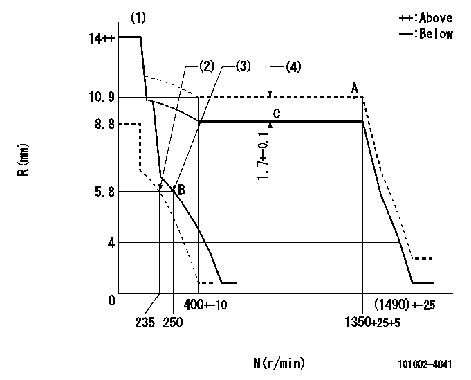
N:Pump speed
R:Rack position (mm)
(1)Notch fixed: K
(2)Set idle sub-spring
(3)Main spring setting
(4)Boost compensator stroke
----------
K=10
----------
----------
K=10
----------
Speed control lever angle

F:Full speed
I:Idle
(1)Stopper bolt setting
----------
----------
a=11deg+-5deg b=29deg+-5deg
----------
----------
a=11deg+-5deg b=29deg+-5deg
Stop lever angle
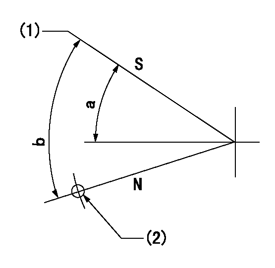
N:Pump normal
S:Stop the pump.
(1)Pump speed aa, rack position bb
(2)Use the hole above R = cc
----------
aa=0r/min bb=1-0.2mm cc=40mm
----------
a=32deg+-5deg b=(55deg)
----------
aa=0r/min bb=1-0.2mm cc=40mm
----------
a=32deg+-5deg b=(55deg)
Timing setting

(1)Pump vertical direction
(2)Position of gear mark 'CC' at No 1 cylinder's beginning of injection
(3)B.T.D.C.: aa
(4)-
----------
aa=(15deg44min)
----------
a=(90deg)
----------
aa=(15deg44min)
----------
a=(90deg)
Information:
Daily or every 8 Hours (whichever occurs first)
Check coolant level.Check oil level in sump (make sure machine is standing level).Check oil pressure (where a gauge is fitted).In extreme dust conditions, clean oil bath air cleaner or empty dust bowl on dry type air cleaner.Every 200 Hours or 4 Months (whichever occurs first)
Clean oil bath air cleaner or empty dust bowl on dry type cleaner.Check drive belt tension.Clean fuel water trap (where fitted).Every 400 Hours or 12 Months (whichever occurs first)
Drain and renew engine lubricating oil.Renew lubricating oil filter canister.Renew final fuel filter element.Clean lift pump sediment chamber.Every 800 Hours
Renew dry type air filter element.Every 2,400 Hours
Arrange for examination and service of proprietary equipment, i.e. starter motor, alternator, etc.Service atomisers.Check and adjust valve clearance.Post-Delivery Checkover
After a customer has taken delivery of his Perkins Diesel engine, a general checkover of the engine must be carried out by an experienced fitter after the first 500/1,000 miles (800/1600 km) or 25/50 hours in service with the engine warm.The checkover should comprise the following points:-1. Drain lubricating oil sump and refill to full mark on dipstick with new oil. See list of Approved Lubricating Oils in Appendix. When the sump is drained and it is possible to gain access to the sump strainer, it is recommended that this be cleaned.2. Renew the lubricating oil filter element.3. Remove the rocker assembly; tighten the cylinder head nuts/setscrews in the correct sequence (see Fig. E.12) and to the correct torque (see Page B.2). (Not necessary for 4.2482 The correct procedure for retightening of cylinder head nuts/setscrews is given on Page E.7. Reset valve tip clearances.4. Check coolant level and check for leaks.5. Check external nuts, setscrews, hose clips, mountings etc. for tightness.6. Check fan belt tension.7. Check electrical equipment and connections.8. Check for lubricating oil leaks.9. Check slow running speed (see Page N.9).10. Check general performance of engine. Routine maintenance should follow as detailed under Preventive Maintenance.Protection of an engine not in service
The recommendations given below are to ensure that damage is prevented when an engine is removed from service for an extended period. Use these procedures immediately the engine is removed from service. The instructions for the use of POWERPART products are given on the outside of each container.1. Thoroughly clean the outside of the engine.2. Where a preservative fuel is to be used, drain the fuel system and fill with the preservative fuel. POWERPART Lay-Up 1 can be added to the normal fuel to change it to a preservative fuel. If preservative fuel is not used, the system can be kept charged with normal fuel but this will have to be drained and discarded at the end of the storage period together with the fuel filter.3. Run the engine until it is warm. Correct any fuel, lubricating oil or air leakage. Stop the engine and drain the lubricating oil sump.4. Renew the lubricating oil filter canister.5. Fill the sump to the full mark on the dipstick with clean new lubricating oil or with