Information injection-pump assembly
ZEXEL
101602-4640
1016024640
ISUZU
1156021380
1156021380

Rating:
Cross reference number
ZEXEL
101602-4640
1016024640
ISUZU
1156021380
1156021380
Zexel num
Bosch num
Firm num
Name
Calibration Data:
Adjustment conditions
Test oil
1404 Test oil ISO4113 or {SAEJ967d}
1404 Test oil ISO4113 or {SAEJ967d}
Test oil temperature
degC
40
40
45
Nozzle and nozzle holder
105780-8140
Bosch type code
EF8511/9A
Nozzle
105780-0000
Bosch type code
DN12SD12T
Nozzle holder
105780-2080
Bosch type code
EF8511/9
Opening pressure
MPa
17.2
Opening pressure
kgf/cm2
175
Injection pipe
Outer diameter - inner diameter - length (mm) mm 6-2-600
Outer diameter - inner diameter - length (mm) mm 6-2-600
Overflow valve opening pressure
kPa
157
123
191
Overflow valve opening pressure
kgf/cm2
1.6
1.25
1.95
Tester oil delivery pressure
kPa
157
157
157
Tester oil delivery pressure
kgf/cm2
1.6
1.6
1.6
Direction of rotation (viewed from drive side)
Right R
Right R
Injection timing adjustment
Direction of rotation (viewed from drive side)
Right R
Right R
Injection order
1-5-3-6-
2-4
Pre-stroke
mm
4.4
4.35
4.45
Beginning of injection position
Drive side NO.1
Drive side NO.1
Difference between angles 1
Cal 1-5 deg. 60 59.5 60.5
Cal 1-5 deg. 60 59.5 60.5
Difference between angles 2
Cal 1-3 deg. 120 119.5 120.5
Cal 1-3 deg. 120 119.5 120.5
Difference between angles 3
Cal 1-6 deg. 180 179.5 180.5
Cal 1-6 deg. 180 179.5 180.5
Difference between angles 4
Cyl.1-2 deg. 240 239.5 240.5
Cyl.1-2 deg. 240 239.5 240.5
Difference between angles 5
Cal 1-4 deg. 300 299.5 300.5
Cal 1-4 deg. 300 299.5 300.5
Injection quantity adjustment
Adjusting point
A
Rack position
10.9
Pump speed
r/min
1350
1350
1350
Average injection quantity
mm3/st.
125.4
123.8
127
Max. variation between cylinders
%
0
-2.5
2.5
Basic
*
Fixing the lever
*
Boost pressure
kPa
100
100
Boost pressure
mmHg
750
750
Injection quantity adjustment_02
Adjusting point
-
Rack position
6.1+-0.5
Pump speed
r/min
250
250
250
Average injection quantity
mm3/st.
9.4
8.1
10.7
Max. variation between cylinders
%
0
-14
14
Fixing the rack
*
Boost pressure
kPa
0
0
0
Boost pressure
mmHg
0
0
0
Remarks
Adjust only variation between cylinders; adjust governor according to governor specifications.
Adjust only variation between cylinders; adjust governor according to governor specifications.
Boost compensator adjustment
Pump speed
r/min
700
700
700
Rack position
9.2
Boost pressure
kPa
12
10.7
13.3
Boost pressure
mmHg
90
80
100
Boost compensator adjustment_02
Pump speed
r/min
700
700
700
Rack position
10.9
Boost pressure
kPa
80
80
80
Boost pressure
mmHg
600
600
600
Test data Ex:
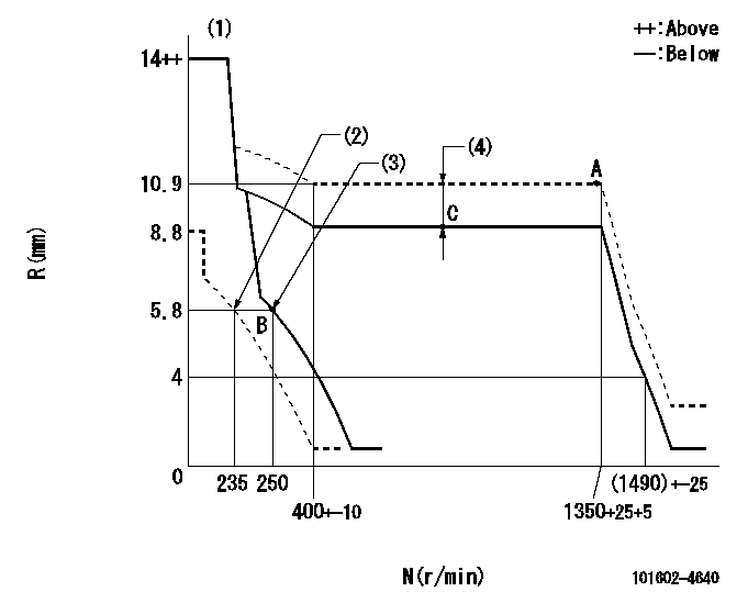
Governor adjustment

N:Pump speed
R:Rack position (mm)
(1)Notch fixed: K
(2)Set idle sub-spring
(3)Main spring setting
(4)Boost compensator stroke: BCL
----------
K=10 BCL=1.7+-0.1mm
----------
----------
K=10 BCL=1.7+-0.1mm
----------
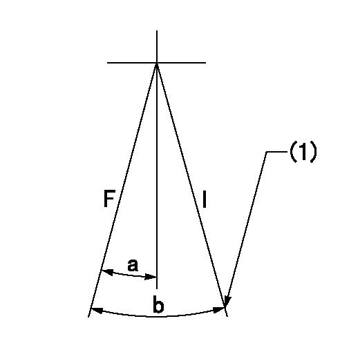
Speed control lever angle

F:Full speed
I:Idle
(1)Stopper bolt setting
----------
----------
a=11deg+-5deg b=29deg+-5deg
----------
----------
a=11deg+-5deg b=29deg+-5deg
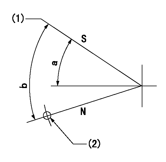
Stop lever angle

N:Pump normal
S:Stop the pump.
(1)Pump speed aa, rack position bb
(2)Use the hole above R = cc
----------
aa=0r/min bb=1-0.2mm cc=40mm
----------
a=32deg+-5deg b=(55deg)
----------
aa=0r/min bb=1-0.2mm cc=40mm
----------
a=32deg+-5deg b=(55deg)
Timing setting

(1)Pump vertical direction
(2)Position of gear mark 'CC' at No 1 cylinder's beginning of injection
(3)B.T.D.C.: aa
(4)-
----------
aa=15deg44min
----------
a=(100deg)
----------
aa=15deg44min
----------
a=(100deg)
Information:
Balancer Unit - Front Mounted
Later units have needle roller bearings and all current balancer units have reversed weights.Front Dia. of Shafts (Driving and Driven) ... 1.2484/1.2490 in(31,71/31,73 mm)Inside Dia. of Front Balance Frame Bushes ... 1.2510/1.2526 in(31,78/31,82 mm)Running Clearance of Shafts in Bushes ... 0.002/0.0042 in(0,05/0,11 mm)Rear Dia. of Shafts (Driving and Driven) ... 0.9987/0.9992 in(25,37/25,38 mm)Inside Dia. of Rear Balance Frame Bushes ... 1.001/1.0022 in(25,43/25,46 mm)Running Clearance of Shafts in Bushes ... 0.0018/0.0035 in(0,05/0,09 mm)Shaft Dia. for Balance Weights ... 1.0622/1.0630 in(26,98/27,00 mm)Bore Dia. of Balance Weights ... 1.0625/1.0637 in(26,99/27,02 mm)Fit of Balance Weights on Shafts ... -0.0005/+0.0015 in(-0,01/+0,04 mm)Spigot Dia. of Earlier Balance Weights ... 2.499/2.500 in(63,47/63,50 mm)Recess Dia. in Earlier Balance Weights ... 2.500/2.501 in(63,50/63,53 mm)Spigot Dia. for Reversed Balance Weights ... 1.374/1.375 in(34,90/34,93 mm)Recess Dia. in Reversed Balance Weight Gears ... 1.375/1.376 in(34,93/34,95 mm)Fit of Gear on Balance Weight ... -0.000/+0.002 in(-0,00/+0,05 mm)Dia. of Earlier Shaft for Lub. Oil Pump Gear ... 0.4215/0.4235 in(10,71/10,76 mm)Bore Dia. of Earlier Lub. Oil Pump Drive Gear ... 0.425/0.426 in(10,79/10,82 mm)Clearance Fit of Earlier Gear on Shaft ... 0.0015/0.0045 in(0,04/0,11 mm)Dia. of Shaft for Later Lub. Oil Pump Gear ... 0.6500/0.6508 in(16,51/16,53 mm)Bore Dia. of Later Lub. Oil Pump Drive Gear ... 0.6513/0.6533 in(16,54/16,59 mm)Clearance Fit of Later Gear on Shaft ... 0.0005/0.0033 in(0,01/0,08 mm)Depth of Earlier Lub. Oil Pump Body ... 0.999/1.002 in(25,38/25,45 mm)Depth of Later Lub. Oil Pump Body ... 1.002/1.005 in(25,45/25,53 mm)Width of Lub. Oil Pump Drive Gears ... 0.998/1.000 in(25,35/25,40 mm)End Float of Earlier Oil Pump Gears (with joint) ... 0.003/0.008 in(0,08/0,20 mm)End Float of Later Oil Pump Gears ... 0.002/0.007 in(0,05/0,18 mm)Shaft Dia. for Lub. Oil Pump Driven Gear ... 0.4382/0.4386 in(11,13/11,14 mm)Bore Dia. of Lub. Oil Pump Driven Gear ... 0.4394/0.4404 in(11,16/11,19 mm)Running Clearance of Oil Pump Driven Gear ... 0.0008/0.0022 in(0,02/0,06 mm)Hub Dia. for Idler Gear ... 1.4984/1.4990 in(38,06/38,08 mm)Bore Dia. of Idler Gear Bush ... 1.500/1.5016 in(38,10/38,14 mm)Running Clearance of Idler Gear on Hub ... 0.001/0.0032 in(0,03/0,08 mm)Idler Gear End Float ... 0.008/0.014 in(0,20/0,36 mm)Balancer Unit - Centre Mounted
No. of Teeth on Driveshaft Gear ... 21Dia. of Driveshaft (at Front Bearing) ... 1.124/1.125 in(28,562/28,575 mm)Dia. of Driveshaft (at Rear Bearing) ... 0.936/0.937 in(23,787/23,800 mm)Dia. of Oil Pump Drive Splines ... 1.124/1.125 in(28,562/28,575 mm)No. of Splines ... 6Dia. of Balance Weight Drive Gear Splines ... 0.650/0.651 in(15,51/15,53 mm)No. of Splines ... 6Dia. of Front Bearing Bore (Driveshaft) ... 1.374/1.375 in(34,912/34,937 mm)Outside Dia. of Front Bearing (Driveshaft) ... 1.3748 in(34,92 mm)Inside Dia. of Front Bearing (Driveshaft) ... 1.125 in(28,58 mm)Dia. of Rear Bearing Bore (Driveshaft) ... 1.800/1.805 in(29,972/29,993 mm)Outside Dia. of Rear Bearing (Driveshaft) ... 1.181 in(30,00 mm)Inside Dia. of Rear Bearing (Driveshaft) ... 0.937 in(23,8 mm)Dia. of Balance Frame and End Frame Bush Bores ... 1.656/1.657 in(42,070/42,095 mm)Outside Dia. of Balance Frame and End Frame Bushes ... 1.66 in(42,164 mm)Inside Dia. of Balance Frame and End Frame Bushes ... 1.501/1.503 in(38,133/38,174 mm)Clearance of Balance Weight Shafts in Bushes ... 0.0025/0.0047 in(0,064/0,120 mm)Shaft Dia. of Balance Weights ... 1.498/1.499 in(38,054/38,069 mm)No. of