Information injection-pump assembly
BOSCH
9 400 614 844
9400614844
ZEXEL
101602-4610
1016024610
ISUZU
1156018700
1156018700

Rating:
Service parts 101602-4610 INJECTION-PUMP ASSEMBLY:
1.
_
5.
AUTOM. ADVANCE MECHANIS
8.
_
9.
_
11.
Nozzle and Holder
1-15300-105-2
12.
Open Pre:MPa(Kqf/cm2)
18.1{185}
15.
NOZZLE SET
Include in #1:
101602-4610
as INJECTION-PUMP ASSEMBLY
Include in #2:
104948-1000
as _
Cross reference number
BOSCH
9 400 614 844
9400614844
ZEXEL
101602-4610
1016024610
ISUZU
1156018700
1156018700
Zexel num
Bosch num
Firm num
Name
101602-4610
9 400 614 844
1156018700 ISUZU
INJECTION-PUMP ASSEMBLY
6BD1T * K 14BE PE6A PE
6BD1T * K 14BE PE6A PE
Calibration Data:
Adjustment conditions
Test oil
1404 Test oil ISO4113 or {SAEJ967d}
1404 Test oil ISO4113 or {SAEJ967d}
Test oil temperature
degC
40
40
45
Nozzle and nozzle holder
105780-8140
Bosch type code
EF8511/9A
Nozzle
105780-0000
Bosch type code
DN12SD12T
Nozzle holder
105780-2080
Bosch type code
EF8511/9
Opening pressure
MPa
17.2
Opening pressure
kgf/cm2
175
Injection pipe
Outer diameter - inner diameter - length (mm) mm 6-2-600
Outer diameter - inner diameter - length (mm) mm 6-2-600
Overflow valve opening pressure
kPa
157
123
191
Overflow valve opening pressure
kgf/cm2
1.6
1.25
1.95
Tester oil delivery pressure
kPa
157
157
157
Tester oil delivery pressure
kgf/cm2
1.6
1.6
1.6
Direction of rotation (viewed from drive side)
Right R
Right R
Injection timing adjustment
Direction of rotation (viewed from drive side)
Right R
Right R
Injection order
1-5-3-6-
2-4
Pre-stroke
mm
3.4
3.35
3.45
Beginning of injection position
Drive side NO.1
Drive side NO.1
Difference between angles 1
Cal 1-5 deg. 60 59.5 60.5
Cal 1-5 deg. 60 59.5 60.5
Difference between angles 2
Cal 1-3 deg. 120 119.5 120.5
Cal 1-3 deg. 120 119.5 120.5
Difference between angles 3
Cal 1-6 deg. 180 179.5 180.5
Cal 1-6 deg. 180 179.5 180.5
Difference between angles 4
Cyl.1-2 deg. 240 239.5 240.5
Cyl.1-2 deg. 240 239.5 240.5
Difference between angles 5
Cal 1-4 deg. 300 299.5 300.5
Cal 1-4 deg. 300 299.5 300.5
Injection quantity adjustment
Adjusting point
A
Rack position
8.5
Pump speed
r/min
800
800
800
Average injection quantity
mm3/st.
74.3
72.3
76.3
Max. variation between cylinders
%
0
-4
4
Fixing the lever
*
Boost pressure
kPa
26.7
26.7
Boost pressure
mmHg
200
200
Injection quantity adjustment_02
Adjusting point
B
Rack position
8.1
Pump speed
r/min
1250
1250
1250
Average injection quantity
mm3/st.
77
75.5
78.5
Max. variation between cylinders
%
0
-2.5
2.5
Basic
*
Fixing the lever
*
Boost pressure
kPa
26.7
26.7
Boost pressure
mmHg
200
200
Injection quantity adjustment_03
Adjusting point
C
Rack position
7.9
Pump speed
r/min
500
500
500
Average injection quantity
mm3/st.
51.2
49.2
53.2
Max. variation between cylinders
%
0
-4
4
Fixing the lever
*
Boost pressure
kPa
0
0
0
Boost pressure
mmHg
0
0
0
Injection quantity adjustment_04
Adjusting point
D
Rack position
5.2+-0.5
Pump speed
r/min
325
325
325
Average injection quantity
mm3/st.
12.1
10.8
13.4
Max. variation between cylinders
%
0
-14
14
Fixing the rack
*
Boost pressure
kPa
0
0
0
Boost pressure
mmHg
0
0
0
Injection quantity adjustment_05
Adjusting point
E
Rack position
8.8+-0.5
Pump speed
r/min
150
150
150
Average injection quantity
mm3/st.
49.2
49.2
Fixing the lever
*
Boost pressure
kPa
0
0
0
Boost pressure
mmHg
0
0
0
Boost compensator adjustment
Pump speed
r/min
700
700
700
Rack position
7.9
Boost pressure
kPa
7.3
2
12.6
Boost pressure
mmHg
55
15
95
Boost compensator adjustment_02
Pump speed
r/min
700
700
700
Rack position
8.6
Boost pressure
kPa
25.3
24
26.6
Boost pressure
mmHg
190
180
200
Test data Ex:
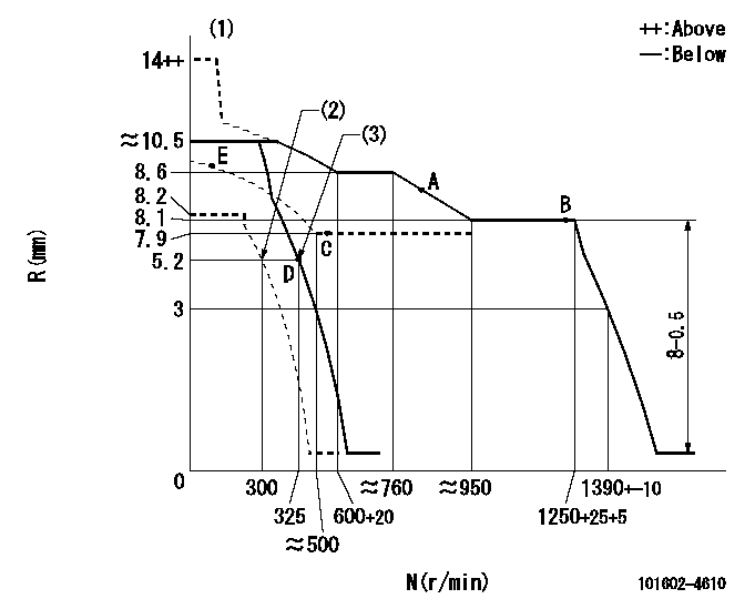
Governor adjustment

N:Pump speed
R:Rack position (mm)
(1)Target notch: K
(2)Set idle sub-spring
(3)Main spring setting
----------
K=13
----------
----------
K=13
----------
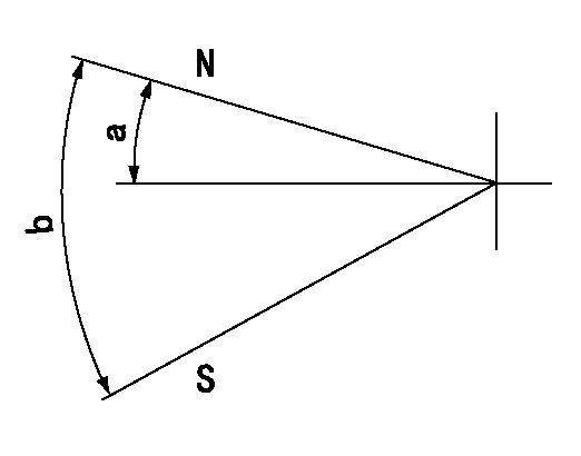
Speed control lever angle

F:Full speed
I:Idle
(1)Stopper bolt setting
----------
----------
a=(11deg)+-5deg b=(29deg)+-5deg
----------
----------
a=(11deg)+-5deg b=(29deg)+-5deg
Stop lever angle

N:Pump normal
S:Stop the pump.
----------
----------
a=12deg+-5deg b=46deg+-5deg
----------
----------
a=12deg+-5deg b=46deg+-5deg
Timing setting

(1)Pump vertical direction
(2)Position of flywheel's threaded hole at No 1 cylinder's beginning of injection
(3)-
(4)-
----------
----------
a=(10deg)
----------
----------
a=(10deg)
Information:
5-9 When moving radial seal, observe correct depth of installation (pressed in). Depth 1 see Fig. 5-9, outside flush with front-end cover.
5-10Depth 2 (after shifting in front-end cover to be flush inside) : max. 1.0 mm.Fig. 5-10Dismantling And Installing The Vee-Belt Tensioner (As from 3 cylinder engine)
Dismantling:
1. Dismantle the holder for the warning system operator. Remove the vee belt driving the cooling air blower.2. Dismantle the vee-belt tensioner. Remove the rubber O-seal on the vee-belt tensioner.Installing:
5-111. Fit a new rubber O-seal on the vee-belt tensioner.Fig. 5-11
5-122. Mount the vee-belt tensioner with the idler pulley facing outwards.Fig. 5-12
5-133. Mount the holder of the warning system operator if the engine is equipped with an alarm system for breakage of the blower belt. Fit a spacer sleeve between the holder and front cover.Fig. 5-13
5-144. Check the alignment of the vee belt running from the idler pulley to the belt pulley mounted on the crankshaft.Fig. 5-145. If misalignment has to be corrected dismantle the vee-belt idler pulley.Checking And Repairing The Vee-Belt Tensioner
Tensioner is removed.
5-151. If the idler is damaged or its bearing worn, dismantle it from the tensioning lever. Check the radial clearance of the shaft of the vee-belt tensioner.Fig. 5-152. If the shaft has too much radial clearance or if the torsion spring is weak or broken, dismantle the vee-belt tensioner.
5-163. After prising out the shaft seal, press out the bearing bushings that are to be renewed. Press in new bearing bushing flush on the inside. Before pressing in the outer bearing bushing, measure the height of the shaft seal and then press in the bearing bushing deeper by this amount.Fig. 5-164. Press in shaft seal flush on outside.
5-175. Renew worn shaft. Drive the heavy-duty clamping sleeve into the large bore so that one end projects 15 mm.Fig. 5-17
5-186. To install, insert the end of the shaft at the inside. Press the end of the torsion spring into the clamping sleeve and push in the shaft completely.Fig. 5-18 If the ends of the torsion spring are of different length, insert the longer one in the clamping sleeve.7. Fit two new gaskets in the groove between the housing and shaft.
5-198. Press the tensioning lever on the shaft so that their holes are in register, with the tensioning lever pointing to the right and the long end of the clamping sleeve pointing downwards (as viewed from inside).Fig. 5-19
5-209. Assemble the idler with the old shims to the tensioning lever.Fig. 5-20Reassembling The Vee-Belt Tensioner (New Design)
Bearing bushing and shaft seal are already fitted.
5-211. Insert long end of torsion spring into shaft and place spacer washer (arrow) in position.Fig. 5-21
5-222. Insert shaft with torsion spring and spacer washer into housing. Position for short end of torsion spring - see arrow.Fig. 5-22
5-233. Push the tensioning lever onto the shaft so that the bores of shaft and lever coincide and the long end of the spring points downwards. Insert locking pin.Fig. 5-23
5-244. Assemble the idler pulley with the old shims to the tensioning lever.Fig. 5-24Dismantling And Installing
Have questions with 101602-4610?
Group cross 101602-4610 ZEXEL
Isuzu
101602-4610
9 400 614 844
1156018700
INJECTION-PUMP ASSEMBLY
6BD1T
6BD1T
