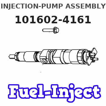
Information injection-pump assembly
BOSCH
9 400 614 831
9400614831
ZEXEL
101602-4161
1016024161
ISUZU
1156015602
1156015602
Rating:
Service parts 101602-4161 INJECTION-PUMP ASSEMBLY:
1.
_
5.
AUTOM. ADVANCE MECHANIS
7.
COUPLING PLATE
8.
_
9.
_
11.
Nozzle and Holder
5-15300-089-1
12.
Open Pre:MPa(Kqf/cm2)
18.1{185}
15.
NOZZLE SET
Cross reference number
BOSCH
9 400 614 831
9400614831
ZEXEL
101602-4161
1016024161
ISUZU
1156015602
1156015602
Zexel num
Bosch num
Firm num
Name
101602-4161
9 400 614 831
1156015602 ISUZU
INJECTION-PUMP ASSEMBLY
6BD1-T K 14BE INJECTION PUMP ASSY PE6A PE
6BD1-T K 14BE INJECTION PUMP ASSY PE6A PE
Calibration Data:
Adjustment conditions
Test oil
1404 Test oil ISO4113 or {SAEJ967d}
1404 Test oil ISO4113 or {SAEJ967d}
Test oil temperature
degC
40
40
45
Nozzle and nozzle holder
105780-8140
Bosch type code
EF8511/9A
Nozzle
105780-0000
Bosch type code
DN12SD12T
Nozzle holder
105780-2080
Bosch type code
EF8511/9
Opening pressure
MPa
17.2
Opening pressure
kgf/cm2
175
Injection pipe
Outer diameter - inner diameter - length (mm) mm 6-2-600
Outer diameter - inner diameter - length (mm) mm 6-2-600
Overflow valve opening pressure
kPa
157
157
157
Overflow valve opening pressure
kgf/cm2
1.6
1.6
1.6
Tester oil delivery pressure
kPa
157
157
157
Tester oil delivery pressure
kgf/cm2
1.6
1.6
1.6
Direction of rotation (viewed from drive side)
Right R
Right R
Injection timing adjustment
Direction of rotation (viewed from drive side)
Right R
Right R
Injection order
1-5-3-6-
2-4
Pre-stroke
mm
3.4
3.35
3.45
Beginning of injection position
Drive side NO.1
Drive side NO.1
Difference between angles 1
Cal 1-5 deg. 60 59.5 60.5
Cal 1-5 deg. 60 59.5 60.5
Difference between angles 2
Cal 1-3 deg. 120 119.5 120.5
Cal 1-3 deg. 120 119.5 120.5
Difference between angles 3
Cal 1-6 deg. 180 179.5 180.5
Cal 1-6 deg. 180 179.5 180.5
Difference between angles 4
Cyl.1-2 deg. 240 239.5 240.5
Cyl.1-2 deg. 240 239.5 240.5
Difference between angles 5
Cal 1-4 deg. 300 299.5 300.5
Cal 1-4 deg. 300 299.5 300.5
Injection quantity adjustment
Adjusting point
A
Rack position
8.5
Pump speed
r/min
800
800
800
Average injection quantity
mm3/st.
74.3
72.3
76.3
Max. variation between cylinders
%
0
-4
4
Fixing the lever
*
Injection quantity adjustment_02
Adjusting point
B
Rack position
8.2
Pump speed
r/min
1000
1000
1000
Average injection quantity
mm3/st.
74
72.5
75.5
Max. variation between cylinders
%
0
-2.5
2.5
Basic
*
Fixing the lever
*
Injection quantity adjustment_03
Adjusting point
C
Rack position
5.2+-0.5
Pump speed
r/min
325
325
325
Average injection quantity
mm3/st.
12.1
10.8
13.4
Max. variation between cylinders
%
0
-14
14
Fixing the rack
*
Remarks
Adjust only variation between cylinders; adjust governor according to governor specifications.
Adjust only variation between cylinders; adjust governor according to governor specifications.
Test data Ex:
Governor adjustment
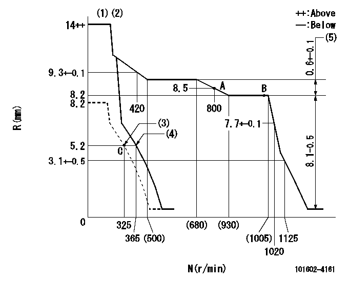
N:Pump speed
R:Rack position (mm)
(1)Target notch: K
(2)Tolerance for racks not indicated: +-0.05mm.
(3)Set idle sub-spring
(4)Main spring setting
(5)Rack difference between N = N1 and N = N2
----------
K=10 N1=1000r/min N2=600r/min
----------
----------
K=10 N1=1000r/min N2=600r/min
----------
Speed control lever angle
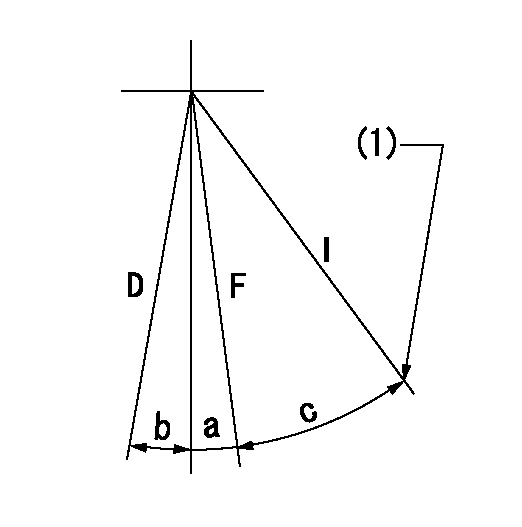
F:Full speed
I:Idle
D:Dead point
(1)Stopper bolt setting
----------
----------
a=3deg+-5deg b=6deg c=17deg+-5deg
----------
----------
a=3deg+-5deg b=6deg c=17deg+-5deg
Stop lever angle

N:Pump normal
S:Stop the pump.
(1)Normal
----------
----------
a=12deg+-5deg b=46deg+-5deg
----------
----------
a=12deg+-5deg b=46deg+-5deg
Timing setting

(1)Pump vertical direction
(2)Position of flywheel's threaded hole at No 1 cylinder's beginning of injection
(3)-
(4)-
----------
----------
a=(10deg)
----------
----------
a=(10deg)
Information:
Do not operate or work on this product unless you have read and understood the instruction and warnings in the relevant Operation and Maintenance Manuals and relevant service literature. Failure to follow the instructions or heed the warnings could result in injury or death. Proper care is your responsibility.
The following changes are adaptable to the products within the listed serial numbers, and are effective with all products after the listed serial numbers.The table below contains the part numbers for this change.
Table 1
Required Parts
Item Qty Part Number Part Name
1 2 303-1968 Gasket
2 4 346-0335 Band Clamp
3 1 422-0219 Exhaust Gasket
4 1 526-7934(1) Catalytic Converter Gp
(1) This part is the serviceable part for either the left or right side DOC.
Have questions with 101602-4161?
Group cross 101602-4161 ZEXEL
Isuzu
101602-4161
9 400 614 831
1156015602
INJECTION-PUMP ASSEMBLY
6BD1-T
6BD1-T