Information injection-pump assembly
ZEXEL
101602-3850
1016023850

Rating:
Service parts 101602-3850 INJECTION-PUMP ASSEMBLY:
1.
_
3.
GOVERNOR
5.
AUTOM. ADVANCE MECHANIS
7.
COUPLING PLATE
8.
_
9.
_
11.
Nozzle and Holder
6138-12-3200
12.
Open Pre:MPa(Kqf/cm2)
21.6{220}
15.
NOZZLE SET
Cross reference number
ZEXEL
101602-3850
1016023850
Zexel num
Bosch num
Firm num
Name
Calibration Data:
Adjustment conditions
Test oil
1404 Test oil ISO4113 or {SAEJ967d}
1404 Test oil ISO4113 or {SAEJ967d}
Test oil temperature
degC
40
40
45
Nozzle and nozzle holder
105780-8140
Bosch type code
EF8511/9A
Nozzle
105780-0000
Bosch type code
DN12SD12T
Nozzle holder
105780-2080
Bosch type code
EF8511/9
Opening pressure
MPa
17.2
Opening pressure
kgf/cm2
175
Injection pipe
Outer diameter - inner diameter - length (mm) mm 6-2-600
Outer diameter - inner diameter - length (mm) mm 6-2-600
Tester oil delivery pressure
kPa
157
157
157
Tester oil delivery pressure
kgf/cm2
1.6
1.6
1.6
Direction of rotation (viewed from drive side)
Right R
Right R
Injection timing adjustment
Direction of rotation (viewed from drive side)
Right R
Right R
Injection order
1-5-3-6-
2-4
Pre-stroke
mm
4
3.95
4.05
Beginning of injection position
Drive side NO.1
Drive side NO.1
Difference between angles 1
Cal 1-5 deg. 60 59.5 60.5
Cal 1-5 deg. 60 59.5 60.5
Difference between angles 2
Cal 1-3 deg. 120 119.5 120.5
Cal 1-3 deg. 120 119.5 120.5
Difference between angles 3
Cal 1-6 deg. 180 179.5 180.5
Cal 1-6 deg. 180 179.5 180.5
Difference between angles 4
Cyl.1-2 deg. 240 239.5 240.5
Cyl.1-2 deg. 240 239.5 240.5
Difference between angles 5
Cal 1-4 deg. 300 299.5 300.5
Cal 1-4 deg. 300 299.5 300.5
Injection quantity adjustment
Adjusting point
A
Rack position
10.7
Pump speed
r/min
900
900
900
Average injection quantity
mm3/st.
103.5
102.5
104.5
Max. variation between cylinders
%
0
-2
2
Basic
*
Fixing the rack
*
Injection quantity adjustment_02
Adjusting point
B
Rack position
8+-0.5
Pump speed
r/min
375
375
375
Average injection quantity
mm3/st.
12.5
11.3
13.7
Max. variation between cylinders
%
0
-10
10
Fixing the rack
*
Test data Ex:
Governor adjustment
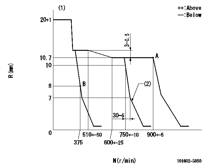
N:Pump speed
R:Rack position (mm)
(1)Target notch: K
(2)Idle sub spring setting: L1.
----------
K=14 L1=7-0.5mm
----------
----------
K=14 L1=7-0.5mm
----------
Speed control lever angle
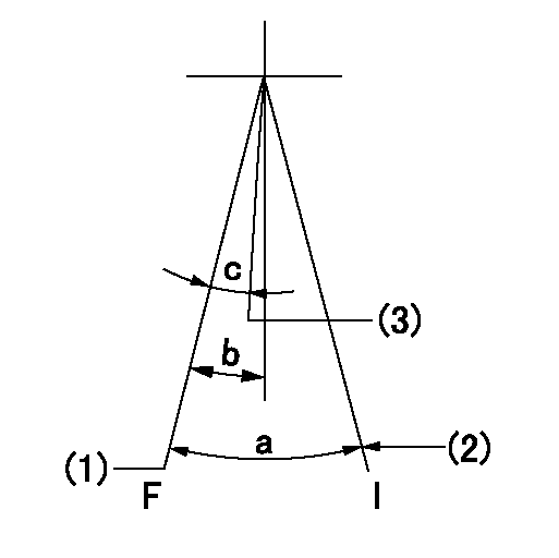
F:Full speed
I:Idle
(1)Set the pump speed at aa. ( At delivery )
(2)Stopper bolt setting
(3)Pump speed = bb
----------
aa=900r/min bb=750r/min
----------
a=27deg+-5deg b=8deg+-5deg c=6deg+-5deg
----------
aa=900r/min bb=750r/min
----------
a=27deg+-5deg b=8deg+-5deg c=6deg+-5deg
Stop lever angle
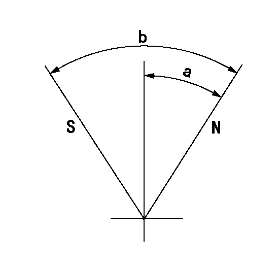
N:Pump normal
S:Stop the pump.
----------
----------
a=27deg+-5deg b=53deg+-5deg
----------
----------
a=27deg+-5deg b=53deg+-5deg
Information:
Introduction
There have been instances of issues with DEF pumps. After analysis, the cause of the issues has been found as contamination with hydrocarbons.Note: Diesel fuel is an example of a hydrocarbon.The DEF filter is equipped with a compensator located in the center of the filter assembly. If the compensator comes into contact with hydrocarbons, the compensator will swell and is designed to block the filter assembly and protect the DEF pump.Solution
The following procedure is designed to diagnose if the DEF pump has been contaminated with hydrocarbons.
Do not operate or work on this product unless you have read and understood the instruction and warnings in the relevant Operation and Maintenance Manuals and relevant service literature. Failure to follow the instructions or heed the warnings could result in injury or death. Proper care is your responsibility.
Ensure that the engine is stopped before any servicing or repair is performed. The Diesel Exhaust Fluid (DEF) system must have completed a proper shutdown. Service on the DEF pump prior to completion of a proper shutdown can result in DEF spray and spillage.
Do not turn off the battery disconnect switch until the indicator lamp has turned off. If the switch is turned off when the indicator lamp is illuminated, the Diesel Exhaust Fluid (DEF) system may not shut down properly. If the DEF system does not shut down properly, DEF could freeze and damage the pump and lines.
Care must be taken to ensure that fluids are contained during performance of inspection, maintenance, testing, adjusting, and repair of the product. Be prepared to collect the fluid with suitable containers before opening any compartment or disassembling any component containing fluids.Refer to Special Publication, NENG2500, "Cat Dealer Service Tool Catalog" or refer to Special Publication, PECJ0003, "Cat Shop Supplies and Tools Catalog" for tools and supplies suitable to collect and contain fluids on Cat products.Dispose of all fluids according to local regulations and mandates.
Note: Clean water should be used to wash spilled DEF off machine components and surfaces.Note: Wear gloves when handling the DEF filter.
Illustration 1 g06278274
(1) Protective cover
Remove protective cover (1).
Illustration 2 g06278289
(2) DEF filter cap
Use a suitable tool to remove DEF filter cap (2).
Illustration 3 g06278325
(3) Compensator
With the filter installed in the DEF pump, carefully remove compensator (3).
Illustration 4 g06614423
(A) 85 mm (3.3 inch)
(B) 17 mm (0.7 inch)
Check the measurements of compensator (3). Check if the measurements are greater than specified in Illustration 4. This condition indicates that the DEF pump is contaminated with hydrocarbons.
If the measurements indicate contamination, replace the DEF pump filter. Refer to Operation and Maintenance Manual, Diesel Exhaust Fluid Filter - Replace.Flush the DEF tank. Refer to Systems Operation, Testing and Adjusting, Diesel Exhaust Fluid Tank - Flush.
If the measurements are within the specification, continue to follow the appropriate troubleshooting procedure to determine if the DEF pump has a fault.