Information injection-pump assembly
BOSCH
9 400 610 116
9400610116
ZEXEL
101602-3780
1016023780
KOMATSU
6136721311
6136721311

Rating:
Service parts 101602-3780 INJECTION-PUMP ASSEMBLY:
1.
_
5.
AUTOM. ADVANCE MECHANIS
7.
COUPLING PLATE
8.
_
9.
_
11.
Nozzle and Holder
6137-12-3100
12.
Open Pre:MPa(Kqf/cm2)
22.1{225}
15.
NOZZLE SET
Cross reference number
BOSCH
9 400 610 116
9400610116
ZEXEL
101602-3780
1016023780
KOMATSU
6136721311
6136721311
Zexel num
Bosch num
Firm num
Name
9 400 610 116
6136721311 KOMATSU
INJECTION-PUMP ASSEMBLY
6D105 K 14BE INJECTION PUMP ASSY PE6A PE
6D105 K 14BE INJECTION PUMP ASSY PE6A PE
Calibration Data:
Adjustment conditions
Test oil
1404 Test oil ISO4113 or {SAEJ967d}
1404 Test oil ISO4113 or {SAEJ967d}
Test oil temperature
degC
40
40
45
Nozzle and nozzle holder
105780-8140
Bosch type code
EF8511/9A
Nozzle
105780-0000
Bosch type code
DN12SD12T
Nozzle holder
105780-2080
Bosch type code
EF8511/9
Opening pressure
MPa
17.2
Opening pressure
kgf/cm2
175
Injection pipe
Outer diameter - inner diameter - length (mm) mm 6-2-600
Outer diameter - inner diameter - length (mm) mm 6-2-600
Tester oil delivery pressure
kPa
157
157
157
Tester oil delivery pressure
kgf/cm2
1.6
1.6
1.6
Direction of rotation (viewed from drive side)
Right R
Right R
Injection timing adjustment
Direction of rotation (viewed from drive side)
Right R
Right R
Injection order
1-5-3-6-
2-4
Pre-stroke
mm
3.3
3.25
3.35
Beginning of injection position
Drive side NO.1
Drive side NO.1
Difference between angles 1
Cal 1-5 deg. 60 59.5 60.5
Cal 1-5 deg. 60 59.5 60.5
Difference between angles 2
Cal 1-3 deg. 120 119.5 120.5
Cal 1-3 deg. 120 119.5 120.5
Difference between angles 3
Cal 1-6 deg. 180 179.5 180.5
Cal 1-6 deg. 180 179.5 180.5
Difference between angles 4
Cyl.1-2 deg. 240 239.5 240.5
Cyl.1-2 deg. 240 239.5 240.5
Difference between angles 5
Cal 1-4 deg. 300 299.5 300.5
Cal 1-4 deg. 300 299.5 300.5
Injection quantity adjustment
Adjusting point
A
Rack position
10.1
Pump speed
r/min
1075
1075
1075
Average injection quantity
mm3/st.
48.5
47.5
49.5
Max. variation between cylinders
%
0
-2
2
Basic
*
Fixing the lever
*
Injection quantity adjustment_02
Adjusting point
B
Rack position
11.3+-0.
5
Pump speed
r/min
800
800
800
Average injection quantity
mm3/st.
57.5
55.5
59.5
Max. variation between cylinders
%
0
-4
4
Fixing the lever
*
Injection quantity adjustment_03
Adjusting point
C
Rack position
7.1+-0.5
Pump speed
r/min
425
425
425
Average injection quantity
mm3/st.
8
7
9
Max. variation between cylinders
%
0
-10
10
Fixing the rack
*
Test data Ex:
Governor adjustment

N:Pump speed
R:Rack position (mm)
(1)Target notch: K
(2)Rack difference between N = N1 and N = N2
----------
K=5 N1=1075r/min N2=800r/min
----------
----------
K=5 N1=1075r/min N2=800r/min
----------
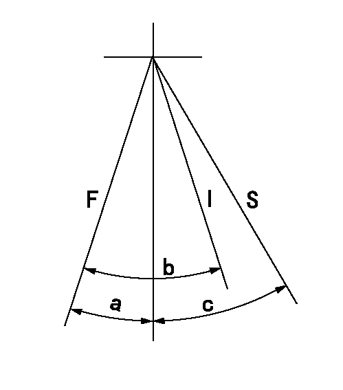
Speed control lever angle

F:Full speed
I:Idle
S:Stop
----------
----------
a=5deg+-5deg b=28deg+-5deg c=32deg+-3deg
----------
----------
a=5deg+-5deg b=28deg+-5deg c=32deg+-3deg
Information:
Introduction
Do not perform any procedure in this Special Instruction until you have read the information and you understand the information.The actuator and pump groups of these fuel injectors are sensitive to debris in the oil. The injector may malfunction due to debris in the oil, causing seizure, or high leaks in components.
Table 1
Revision Table
Revision Summary of Changes
3 Added serial numbers. Improvement Procedure
Clean oil rail after pump failure.Reference: Refer to Special Instruction, REHS3819 for the procedure to clean the oil rail after engine failure to avoid debris in the oil system.
Use clean oil and clean filters.The life of the injector depends on the oil quality. It can be increased if good cleaning practices are performed before installing the injectors.Reference: Refer to Operation and Maintenance Manual, SEBU6250 and Operation and Maintenance Manual, SEBU6251 for direction on oil sampling intervals and optimizing engine oil life.
Illustration 1 g06207717
(1) Actuator
(2) Pump Group
(3) Valve Seat Damage Due to Debris in the Oil SystemInjector Failure Due To Damage From Debris In The Oil May Not Be A Warrantable Failure
Illustration 2 g06244961

