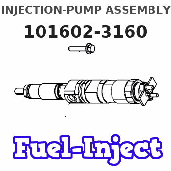
Information injection-pump assembly
BOSCH
9 400 614 814
9400614814
ZEXEL
101602-3160
1016023160
KOMATSU
6136711520
6136711520
Rating:
Include in #1:
101481-0231
as _
Cross reference number
BOSCH
9 400 614 814
9400614814
ZEXEL
101602-3160
1016023160
KOMATSU
6136711520
6136711520
Zexel num
Bosch num
Firm num
Name
101602-3160
9 400 614 814
6136711520 KOMATSU
INJECTION-PUMP ASSEMBLY
6D105 * K 14BE INJECTION PUMP ASSY PE6A PE
6D105 * K 14BE INJECTION PUMP ASSY PE6A PE
Calibration Data:
Adjustment conditions
Test oil
1404 Test oil ISO4113 or {SAEJ967d}
1404 Test oil ISO4113 or {SAEJ967d}
Test oil temperature
degC
40
40
45
Nozzle and nozzle holder
105780-8140
Bosch type code
EF8511/9A
Nozzle
105780-0000
Bosch type code
DN12SD12T
Nozzle holder
105780-2080
Bosch type code
EF8511/9
Opening pressure
MPa
17.2
Opening pressure
kgf/cm2
175
Injection pipe
Outer diameter - inner diameter - length (mm) mm 6-2-600
Outer diameter - inner diameter - length (mm) mm 6-2-600
Tester oil delivery pressure
kPa
157
157
157
Tester oil delivery pressure
kgf/cm2
1.6
1.6
1.6
Direction of rotation (viewed from drive side)
Right R
Right R
Injection timing adjustment
Direction of rotation (viewed from drive side)
Right R
Right R
Injection order
1-5-3-6-
2-4
Pre-stroke
mm
3.5
3.45
3.55
Beginning of injection position
Drive side NO.1
Drive side NO.1
Difference between angles 1
Cal 1-5 deg. 60 59.5 60.5
Cal 1-5 deg. 60 59.5 60.5
Difference between angles 2
Cal 1-3 deg. 120 119.5 120.5
Cal 1-3 deg. 120 119.5 120.5
Difference between angles 3
Cal 1-6 deg. 180 179.5 180.5
Cal 1-6 deg. 180 179.5 180.5
Difference between angles 4
Cyl.1-2 deg. 240 239.5 240.5
Cyl.1-2 deg. 240 239.5 240.5
Difference between angles 5
Cal 1-4 deg. 300 299.5 300.5
Cal 1-4 deg. 300 299.5 300.5
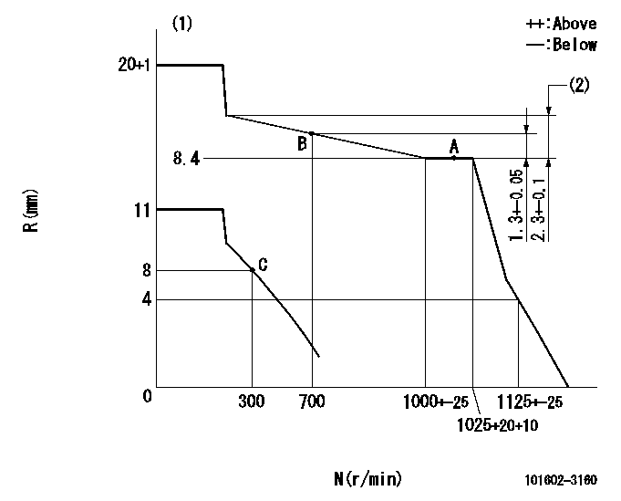
Injection quantity adjustment
Adjusting point
A
Rack position
8.4
Pump speed
r/min
1025
1025
1025
Average injection quantity
mm3/st.
44
43
45
Max. variation between cylinders
%
0
-2
2
Basic
*
Fixing the lever
*
Injection quantity adjustment_02
Adjusting point
C
Rack position
8+-0.5
Pump speed
r/min
300
300
300
Average injection quantity
mm3/st.
10.3
8.8
11.8
Max. variation between cylinders
%
0
-10
10
Fixing the rack
*
Test data Ex:
Governor adjustment
N:Pump speed
R:Rack position (mm)
(1)Target notch: K
(2)Torque control stroke
----------
K=17
----------
----------
K=17
----------
Speed control lever angle
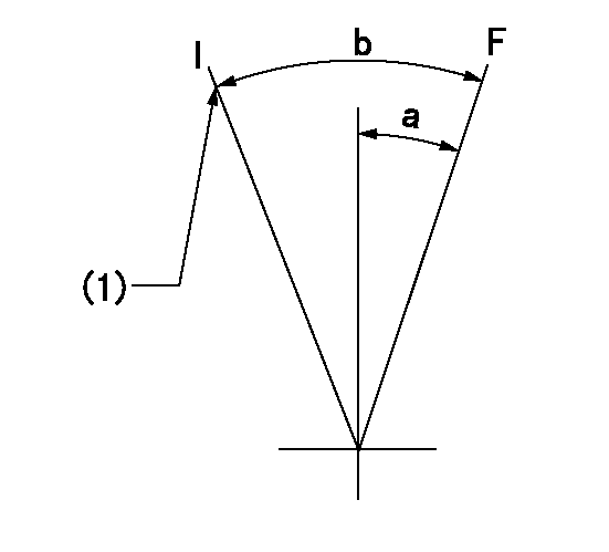
F:Full speed
I:Idle
(1)Stopper bolt setting
----------
----------
a=10deg+-5deg b=24deg+-5deg
----------
----------
a=10deg+-5deg b=24deg+-5deg
Stop lever angle

N:Pump normal
S:Stop the pump.
----------
----------
a=(27deg) b=(53deg)
----------
----------
a=(27deg) b=(53deg)
Information:
Do not operate or work on this product unless you have read and understood the instruction and warnings in the relevant Operation and Maintenance Manuals and relevant service literature. Failure to follow the instructions or heed the warnings could result in injury or death. Proper care is your responsibility.
Improved Diesel Exhaust Fluid (DEF) cooling line clamps are adaptable to the product within the listed serial numbers and are effective with all the product after the listed serial numbers.
Table 1
Required Parts
Item Qty Part Number Part Name Former Part Number(1)
1 10 577-7966 Clamp 520-7003
(1) The former part number listed is for reference only and may differ.
Table 2
Required Tool
Qty Part Number Part Name
1 522-3730 Pliers
Illustration 1 g06408909
View of 398-6108 Cooling Lines Gp
(1) 577-7966 ClampInstall new clamps (1) in 398-6108 Cooling Lines Gp.Note: Ensure 522-3730 Pliers tool is used to install new clamp.
Illustration 2 g06408916
(1) 577-7966 Clamp
(A) Hose
(D1) 5 mm (0.20 inch)Position clamp (1) within 5 mm (0.20 inch) of the bead and perpendicular to the hose axis. If the hose insertion length permits, another clamp can be installed to ensure fluid retention.
Have questions with 101602-3160?
Group cross 101602-3160 ZEXEL
Komatsu
101602-3160
9 400 614 814
6136711520
INJECTION-PUMP ASSEMBLY
6D105
6D105