Information injection-pump assembly
BOSCH
9 400 612 416
9400612416
ZEXEL
101602-2991
1016022991
HINO
220205570A
220205570a
Rating:
Service parts 101602-2991 INJECTION-PUMP ASSEMBLY:
1.
_
5.
AUTOM. ADVANCE MECHANIS
6.
COUPLING PLATE
8.
_
9.
_
11.
Nozzle and Holder
23600-2142A
12.
Open Pre:MPa(Kqf/cm2)
19.6{200}
15.
NOZZLE SET
Cross reference number
BOSCH
9 400 612 416
9400612416
ZEXEL
101602-2991
1016022991
HINO
220205570A
220205570a
Zexel num
Bosch num
Firm num
Name
101602-2991
9 400 612 416
220205570A HINO
INJECTION-PUMP ASSEMBLY
W06EJ K
W06EJ K
Calibration Data:
Adjustment conditions
Test oil
1404 Test oil ISO4113 or {SAEJ967d}
1404 Test oil ISO4113 or {SAEJ967d}
Test oil temperature
degC
40
40
45
Nozzle and nozzle holder
105780-8140
Bosch type code
EF8511/9A
Nozzle
105780-0000
Bosch type code
DN12SD12T
Nozzle holder
105780-2080
Bosch type code
EF8511/9
Opening pressure
MPa
17.2
Opening pressure
kgf/cm2
175
Injection pipe
Outer diameter - inner diameter - length (mm) mm 6-2-600
Outer diameter - inner diameter - length (mm) mm 6-2-600
Overflow valve
134424-0920
Overflow valve opening pressure
kPa
162
147
177
Overflow valve opening pressure
kgf/cm2
1.65
1.5
1.8
Tester oil delivery pressure
kPa
157
157
157
Tester oil delivery pressure
kgf/cm2
1.6
1.6
1.6
Direction of rotation (viewed from drive side)
Right R
Right R
Injection timing adjustment
Direction of rotation (viewed from drive side)
Right R
Right R
Injection order
1-4-2-6-
3-5
Pre-stroke
mm
3.45
3.42
3.48
Beginning of injection position
Drive side NO.1
Drive side NO.1
Difference between angles 1
Cal 1-4 deg. 60 59.75 60.25
Cal 1-4 deg. 60 59.75 60.25
Difference between angles 2
Cyl.1-2 deg. 120 119.75 120.25
Cyl.1-2 deg. 120 119.75 120.25
Difference between angles 3
Cal 1-6 deg. 180 179.75 180.25
Cal 1-6 deg. 180 179.75 180.25
Difference between angles 4
Cal 1-3 deg. 240 239.75 240.25
Cal 1-3 deg. 240 239.75 240.25
Difference between angles 5
Cal 1-5 deg. 300 299.75 300.25
Cal 1-5 deg. 300 299.75 300.25
Injection quantity adjustment
Adjusting point
A
Rack position
11
Pump speed
r/min
900
900
900
Average injection quantity
mm3/st.
69
67
71
Max. variation between cylinders
%
0
-3
3
Basic
*
Fixing the rack
*
Injection quantity adjustment_02
Adjusting point
C
Rack position
7.5+-0.5
Pump speed
r/min
450
450
450
Average injection quantity
mm3/st.
9
7.5
10.5
Max. variation between cylinders
%
0
-15
15
Fixing the rack
*
Injection quantity adjustment_03
Adjusting point
D
Rack position
-
Pump speed
r/min
100
100
100
Average injection quantity
mm3/st.
90
90
100
Fixing the lever
*
Rack limit
*
Test data Ex:
Governor adjustment
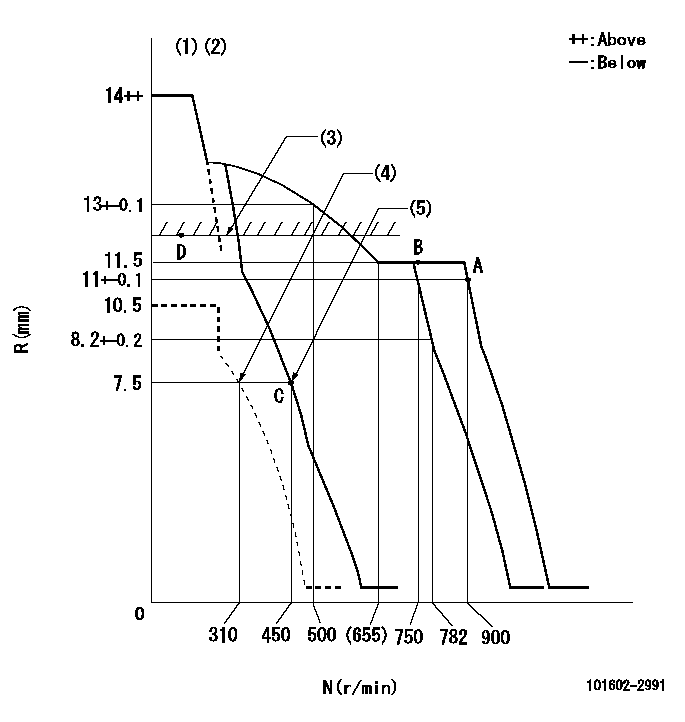
N:Pump speed
R:Rack position (mm)
(1)Target notch: K
(2)Tolerance for racks not indicated: +-0.05mm.
(3)RACK LIMIT
(4)Set idle sub-spring
(5)Main spring setting
----------
K=6
----------
----------
K=6
----------
Speed control lever angle
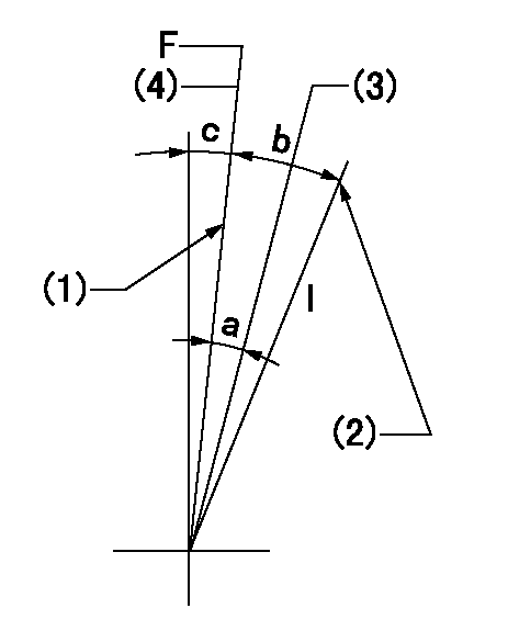
F:Full speed
I:Idle
(1)Stopper bolt setting
(2)Stopper bolt setting
(3)When pump speed set at aa
(4)Set the pump speed at bb.
----------
aa=750r/min bb=900r/min
----------
a=5deg+-5deg b=18deg+-5deg c=2deg+-5deg
----------
aa=750r/min bb=900r/min
----------
a=5deg+-5deg b=18deg+-5deg c=2deg+-5deg
Stop lever angle
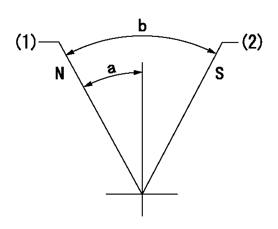
N:Pump normal
S:Stop the pump.
(1)Normal
(2)Rack position aa or less, pump speed bb
----------
aa=7mm bb=0r/min
----------
a=27deg+-5deg b=53deg+-5deg
----------
aa=7mm bb=0r/min
----------
a=27deg+-5deg b=53deg+-5deg
Timing setting

(1)Pump vertical direction
(2)Position of gear's standard threaded hole at No 1 cylinder's beginning of injection
(3)-
(4)-
----------
----------
a=(70deg)
----------
----------
a=(70deg)
Information:
General Operation Guidelines
For Generator Set Installations of Cat DPF Filter Systems
Ensure that the engine operation will adhere to the Cat DPF Filter ARB verification guidelines below:
At least 30 percent of the operating time the exhaust temperature is above 300° C (572° F) and the engine load is above 40 percent.
Fuel sulfur content is less than 15 ppm, ULSD
Engine PM output of less than 0.2 g/bhp-hr
Insulate all exhaust components between the turbocharger and Cat DPF Filter inlet. This inspection includes piping, expansion joints, and bellows.
Install the Cat DLAS monitor/alarm system as the monitoring/alarm system is the key component to ensuring the Cat DPF Filter unit is working as intended. The monitoring/alarm system also ensures that the filter media is not plugging up with particulate matter. This unit records date, time, temperature and backpressure data, allowing the user a comprehensive understanding of engine duty cycle and Cat DPF Filter performance. Follow the installation instructions carefully. Check the integrity of all plumbing and wiring connections. Once installed, download data using the optional software and check that the temperature and backpressure data correspond to engine load output.
Investigate all warnings that the Cat DLAS generates. Solid yellow or red alarms indicate an increase in backpressure and must be investigated. Blinking yellow or red lights indicate a problem with temperature or pressure measurements and require physical checks of the sensors and connections. Data must be collected when an error is generated.
The data stored in the DLAS is easily down loaded using an Ethernet browser and is required to see real-time data and stored data. This data can then be transferred into Microsoft Excel for viewing and graphing. The data includes a history of all errors generated plus 26,000 lines of temperature, backpressure, time, and date values. This data equates to approximately 100 hours of operation when the logging interval is set at 30 seconds.
Create a schedule for downloading Cat DLAS data and graphing the performance. Backpressure may go up and down but over time should be flat, meaning that particulate is not accumulating on the Cat DPF Filter. If particulate is not accumulating, the Cat DPF Filter is said to be regenerating, or self cleaning. This process is the intended operation of regeneration.
DO NOT operate the generator after a red alarm is triggered. Monitor the backpressure during operation using the Cat DLAS interface to an Ethernet browser or a pressure gauge. If the backpressure continues to increase, stop the engine as soon as possible, and allow the exhaust to cool. Remove the Cat DPF Filter for cleaning. If the backpressure decreases, the engine may continue operation until the backpressure has stabilized. Consult your local Cat dealer.
Continuous low load operation should be limited to under 2 hours. After 2 hours but less than 4 hours, and if no alarms have been triggered, regenerate the Cat DPF Filter by operating the engine at 80 percent to 100 percent load for 45 minutes. The Cat DPF can also be removed for cleaning off the machine or engine.
If
Have questions with 101602-2991?
Group cross 101602-2991 ZEXEL
Hino
Hino
Hino
Hino
Hino
Hino
Hino
Hino
101602-2991
9 400 612 416
220205570A
INJECTION-PUMP ASSEMBLY
W06EJ
W06EJ