Information injection-pump assembly
ZEXEL
101602-2941
1016022941
HINO
220205232A
220205232a
Rating:
Cross reference number
ZEXEL
101602-2941
1016022941
HINO
220205232A
220205232a
Zexel num
Bosch num
Firm num
Name
Calibration Data:
Adjustment conditions
Test oil
1404 Test oil ISO4113 or {SAEJ967d}
1404 Test oil ISO4113 or {SAEJ967d}
Test oil temperature
degC
40
40
45
Nozzle and nozzle holder
105780-8140
Bosch type code
EF8511/9A
Nozzle
105780-0000
Bosch type code
DN12SD12T
Nozzle holder
105780-2080
Bosch type code
EF8511/9
Opening pressure
MPa
17.2
Opening pressure
kgf/cm2
175
Injection pipe
Outer diameter - inner diameter - length (mm) mm 6-2-600
Outer diameter - inner diameter - length (mm) mm 6-2-600
Overflow valve
131425-0620
Overflow valve opening pressure
kPa
255
221
289
Overflow valve opening pressure
kgf/cm2
2.6
2.25
2.95
Tester oil delivery pressure
kPa
157
157
157
Tester oil delivery pressure
kgf/cm2
1.6
1.6
1.6
Direction of rotation (viewed from drive side)
Left L
Left L
Injection timing adjustment
Direction of rotation (viewed from drive side)
Left L
Left L
Injection order
1-4-2-6-
3-5
Pre-stroke
mm
3.8
3.77
3.83
Beginning of injection position
Governor side NO.1
Governor side NO.1
Difference between angles 1
Cal 1-4 deg. 60 59.75 60.25
Cal 1-4 deg. 60 59.75 60.25
Difference between angles 2
Cyl.1-2 deg. 120 119.75 120.25
Cyl.1-2 deg. 120 119.75 120.25
Difference between angles 3
Cal 1-6 deg. 180 179.75 180.25
Cal 1-6 deg. 180 179.75 180.25
Difference between angles 4
Cal 1-3 deg. 240 239.75 240.25
Cal 1-3 deg. 240 239.75 240.25
Difference between angles 5
Cal 1-5 deg. 300 299.75 300.25
Cal 1-5 deg. 300 299.75 300.25
Injection quantity adjustment
Adjusting point
A
Rack position
8.8
Pump speed
r/min
900
900
900
Average injection quantity
mm3/st.
87
85
89
Max. variation between cylinders
%
0
-3.5
3.5
Basic
*
Fixing the lever
*
Boost pressure
kPa
42.7
42.7
Boost pressure
mmHg
320
320
Injection quantity adjustment_02
Adjusting point
C
Rack position
6.3+-0.5
Pump speed
r/min
365
365
365
Average injection quantity
mm3/st.
8.5
7.5
9.5
Max. variation between cylinders
%
0
-10
10
Fixing the rack
*
Boost pressure
kPa
0
0
0
Boost pressure
mmHg
0
0
0
Injection quantity adjustment_03
Adjusting point
E
Rack position
-
Pump speed
r/min
100
100
100
Average injection quantity
mm3/st.
105
105
115
Fixing the lever
*
Boost pressure
kPa
0
0
0
Boost pressure
mmHg
0
0
0
Rack limit
*
Boost compensator adjustment
Pump speed
r/min
800
800
800
Rack position
R1-1.9
Boost pressure
kPa
4.7
3.4
6
Boost pressure
mmHg
35
25
45
Boost compensator adjustment_02
Pump speed
r/min
800
800
800
Rack position
R1(8.8)
Boost pressure
kPa
29.3
22.6
36
Boost pressure
mmHg
220
170
270
Test data Ex:
Governor adjustment
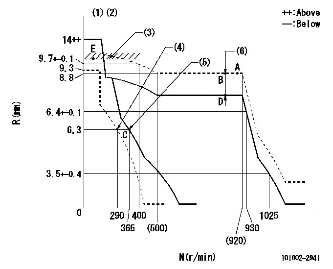
N:Pump speed
R:Rack position (mm)
(1)Target notch: K
(2)Tolerance for racks not indicated: +-0.05mm.
(3)RACK LIMIT
(4)Set idle sub-spring
(5)Main spring setting
(6)Boost compensator stroke: BCL
----------
K=6 BCL=1.9+-0.1mm
----------
----------
K=6 BCL=1.9+-0.1mm
----------
Speed control lever angle
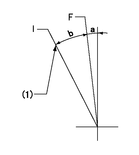
F:Full speed
I:Idle
(1)Stopper bolt setting
----------
----------
a=5deg+-5deg b=17deg+-5deg
----------
----------
a=5deg+-5deg b=17deg+-5deg
Stop lever angle
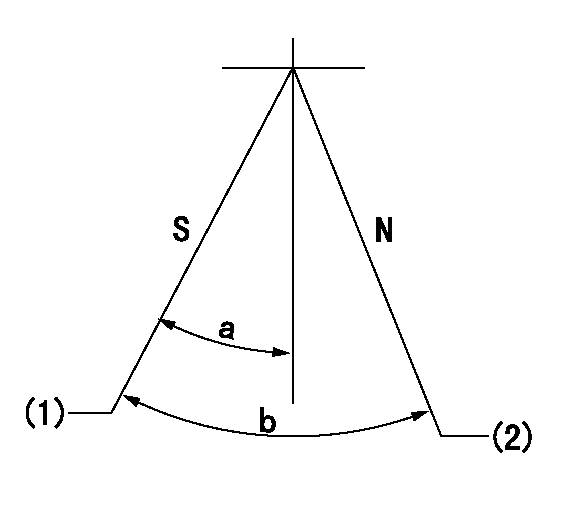
N:Pump normal
S:Stop the pump.
(1)Pump speed aa and rack position bb (to be sealed at delivery)
(2)Normal
----------
aa=0r/min bb=1-0.5mm
----------
a=21deg+-5deg b=(55deg)
----------
aa=0r/min bb=1-0.5mm
----------
a=21deg+-5deg b=(55deg)
Timing setting

(1)Pump vertical direction
(2)Coupling's key groove position at No 1 cylinder's beginning of injection
(3)-
(4)-
----------
----------
a=(20deg)
----------
----------
a=(20deg)
Information:
Do not operate or work on this product unless you have read and understood the instruction and warnings in the relevant Operation and Maintenance Manuals and relevant service literature. Failure to follow the instructions or heed the warnings could result in injury or death. Proper care is your responsibility.
There have been instances of diagnostic code E931 - Aftertreatment#1 SCR Dosing Reagent Absolute Pressure : Low (4334-18 - Aftertreatment #1 DEF #1 Pressure (absolute) : Low – moderate severity) becoming active. This code can be generated by a blocked 495-1507 Diesel Exhaust Fluid Filter Gp, due to the filter not being replaced at the correct maintenance interval.The maintenance interval schedule for the DEF pump filter is every 1500 hours. Ensure that the filter is replaced at the correct service interval. Refer to Operation and Maintenance Manual, Maintenance Interval Schedule for the correct procedure.