Information injection-pump assembly
BOSCH
9 400 613 050
9400613050
ZEXEL
101602-2930
1016022930
HINO
220205390A
220205390a

Rating:
Service parts 101602-2930 INJECTION-PUMP ASSEMBLY:
1.
_
5.
AUTOM. ADVANCE MECHANIS
7.
COUPLING PLATE
8.
_
9.
_
11.
Nozzle and Holder
23600-2710A
12.
Open Pre:MPa(Kqf/cm2)
17.7{180}
15.
NOZZLE SET
Cross reference number
BOSCH
9 400 613 050
9400613050
ZEXEL
101602-2930
1016022930
HINO
220205390A
220205390a
Zexel num
Bosch num
Firm num
Name
101602-2930
9 400 613 050
220205390A HINO
INJECTION-PUMP ASSEMBLY
H07C-TD K
H07C-TD K
Calibration Data:
Adjustment conditions
Test oil
1404 Test oil ISO4113 or {SAEJ967d}
1404 Test oil ISO4113 or {SAEJ967d}
Test oil temperature
degC
40
40
45
Nozzle and nozzle holder
105780-8140
Bosch type code
EF8511/9A
Nozzle
105780-0000
Bosch type code
DN12SD12T
Nozzle holder
105780-2080
Bosch type code
EF8511/9
Opening pressure
MPa
17.2
Opening pressure
kgf/cm2
175
Injection pipe
Outer diameter - inner diameter - length (mm) mm 6-2-600
Outer diameter - inner diameter - length (mm) mm 6-2-600
Overflow valve
134424-0920
Overflow valve opening pressure
kPa
162
147
177
Overflow valve opening pressure
kgf/cm2
1.65
1.5
1.8
Tester oil delivery pressure
kPa
157
157
157
Tester oil delivery pressure
kgf/cm2
1.6
1.6
1.6
Direction of rotation (viewed from drive side)
Right R
Right R
Injection timing adjustment
Direction of rotation (viewed from drive side)
Right R
Right R
Injection order
1-4-2-6-
3-5
Pre-stroke
mm
4.8
4.77
4.83
Beginning of injection position
Drive side NO.1
Drive side NO.1
Difference between angles 1
Cal 1-4 deg. 60 59.75 60.25
Cal 1-4 deg. 60 59.75 60.25
Difference between angles 2
Cyl.1-2 deg. 120 119.75 120.25
Cyl.1-2 deg. 120 119.75 120.25
Difference between angles 3
Cal 1-6 deg. 180 179.75 180.25
Cal 1-6 deg. 180 179.75 180.25
Difference between angles 4
Cal 1-3 deg. 240 239.75 240.25
Cal 1-3 deg. 240 239.75 240.25
Difference between angles 5
Cal 1-5 deg. 300 299.75 300.25
Cal 1-5 deg. 300 299.75 300.25
Injection quantity adjustment
Adjusting point
A
Rack position
9.1
Pump speed
r/min
900
900
900
Average injection quantity
mm3/st.
84
82
86
Max. variation between cylinders
%
0
-3.5
3.5
Basic
*
Fixing the lever
*
Injection quantity adjustment_02
Adjusting point
C
Rack position
6.8+-0.5
Pump speed
r/min
360
360
360
Average injection quantity
mm3/st.
8.5
7.5
9.5
Max. variation between cylinders
%
0
-10
10
Fixing the rack
*
Injection quantity adjustment_03
Adjusting point
E
Rack position
-
Pump speed
r/min
100
100
100
Average injection quantity
mm3/st.
135
135
145
Fixing the lever
*
Rack limit
*
Test data Ex:
Governor adjustment
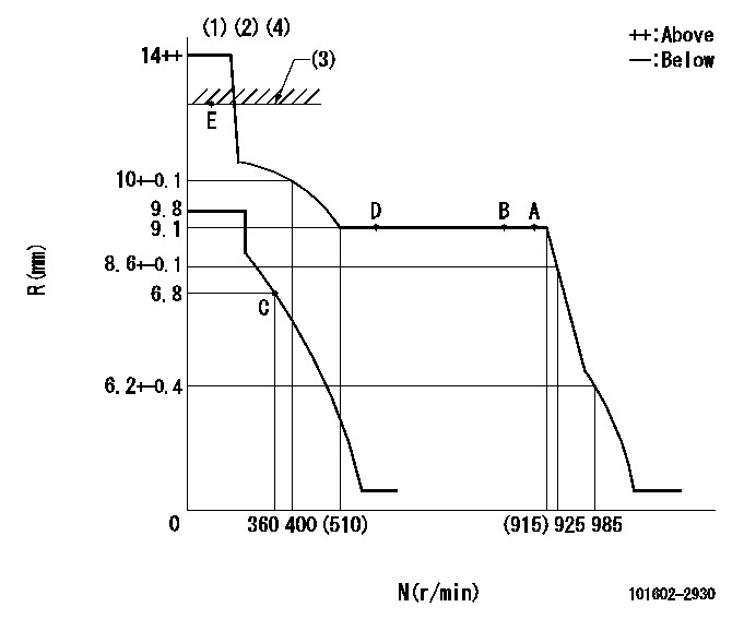
N:Pump speed
R:Rack position (mm)
(1)Target notch: K
(2)Tolerance for racks not indicated: +-0.05mm.
(3)RACK LIMIT
(4)Boost compensator adjustment not effective
----------
K=9
----------
----------
K=9
----------
Speed control lever angle

F:Full speed
I:Idle
(1)Stopper bolt setting
----------
----------
a=3deg+-5deg b=26deg+-5deg
----------
----------
a=3deg+-5deg b=26deg+-5deg
Stop lever angle

N:Pump normal
S:Stop the pump.
(1)Pump speed aa and rack position bb (to be sealed at delivery)
----------
aa=0r/min bb=1-0.5mm
----------
a=21deg+-5deg b=(55deg)
----------
aa=0r/min bb=1-0.5mm
----------
a=21deg+-5deg b=(55deg)
Timing setting

(1)Pump vertical direction
(2)Coupling's key groove position at No 1 cylinder's beginning of injection
(3)-
(4)-
----------
----------
a=(50deg)
----------
----------
a=(50deg)
Information:
Do not operate or work on this product unless you have read and understood the instruction and warnings in the relevant Operation and Maintenance Manuals and relevant service literature. Failure to follow the instructions or heed the warnings could result in injury or death. Proper care is your responsibility.
The following changes are adaptable to machines within the listed serial numbers and are effective with all machines after the listed serial numbers.
Illustration 1 g06325715
View of Air lines group on 966M, 972M, 966M XE, and 972M XE machines
(1) 415-8220 Hose
(2) 8T-6703 Hose Clamp
(3) 211-8073 Protection Cap
Illustration 2 g06325708
View of Air lines group on 980M and 982M machines
(1) 365-0045 Hose
(2) 8T-6703 Hose Clamp
(3) 211-8073 Protection Cap
Table 1
Required Parts
Item Qty New Part Number Part Name Former Part Number
1 1 415-8220 (1) Hose 415-8220
365-0045 (2) 365-0045
2 2 8T-6703 Hose Clamp (3) 296-5807
3 2 211-8073 Protection Cap 7X-1443
(1) For 966M, 972M, 966M XE, and 972M XE machines
(2) For 980M and 982M machines
(3) Torque for the hose clamps is 11 2 N m (97 18 lb in).If the CRS hose is found damaged on the above listed machines, replace the hose with same part number. Use hose clamp (2) and protection cap (3) to secure the new hose.The new hose clamp (2) replaces the existing 296-5807 Clamp. The new protection cap (3) replaces the existing 7X-1443 Protector on machines listed above.Torque the hose clamps (2) to 11 2 N m (97 18 lb in).
Have questions with 101602-2930?
Group cross 101602-2930 ZEXEL
Hino
Hino
Hino
Hino
101602-2930
9 400 613 050
220205390A
INJECTION-PUMP ASSEMBLY
H07C-TD
H07C-TD