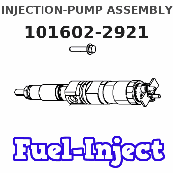
Information injection-pump assembly
ZEXEL
101602-2921
1016022921
Rating:
Cross reference number
ZEXEL
101602-2921
1016022921
Zexel num
Bosch num
Firm num
Name
101602-2921
INJECTION-PUMP ASSEMBLY
Calibration Data:
Adjustment conditions
Test oil
1404 Test oil ISO4113 or {SAEJ967d}
1404 Test oil ISO4113 or {SAEJ967d}
Test oil temperature
degC
40
40
45
Nozzle and nozzle holder
105780-8140
Bosch type code
EF8511/9A
Nozzle
105780-0000
Bosch type code
DN12SD12T
Nozzle holder
105780-2080
Bosch type code
EF8511/9
Opening pressure
MPa
17.2
Opening pressure
kgf/cm2
175
Injection pipe
Outer diameter - inner diameter - length (mm) mm 6-2-600
Outer diameter - inner diameter - length (mm) mm 6-2-600
Overflow valve
134424-0920
Overflow valve opening pressure
kPa
162
147
177
Overflow valve opening pressure
kgf/cm2
1.65
1.5
1.8
Tester oil delivery pressure
kPa
157
157
157
Tester oil delivery pressure
kgf/cm2
1.6
1.6
1.6
Direction of rotation (viewed from drive side)
Right R
Right R
Injection timing adjustment
Direction of rotation (viewed from drive side)
Right R
Right R
Injection order
1-4-2-6-
3-5
Pre-stroke
mm
4.8
4.77
4.83
Beginning of injection position
Drive side NO.1
Drive side NO.1
Difference between angles 1
Cal 1-4 deg. 60 59.75 60.25
Cal 1-4 deg. 60 59.75 60.25
Difference between angles 2
Cyl.1-2 deg. 120 119.75 120.25
Cyl.1-2 deg. 120 119.75 120.25
Difference between angles 3
Cal 1-6 deg. 180 179.75 180.25
Cal 1-6 deg. 180 179.75 180.25
Difference between angles 4
Cal 1-3 deg. 240 239.75 240.25
Cal 1-3 deg. 240 239.75 240.25
Difference between angles 5
Cal 1-5 deg. 300 299.75 300.25
Cal 1-5 deg. 300 299.75 300.25
Injection quantity adjustment
Adjusting point
A
Rack position
9.4
Pump speed
r/min
900
900
900
Average injection quantity
mm3/st.
92.5
91
94
Max. variation between cylinders
%
0
-3.5
3.5
Basic
*
Fixing the rack
*
Injection quantity adjustment_02
Adjusting point
-
Rack position
6.9+-0.5
Pump speed
r/min
400
400
400
Average injection quantity
mm3/st.
10.5
9.5
11.5
Max. variation between cylinders
%
0
-10
10
Fixing the rack
*
Remarks
Adjust only variation between cylinders; adjust governor according to governor specifications.
Adjust only variation between cylinders; adjust governor according to governor specifications.
Injection quantity adjustment_03
Adjusting point
E
Rack position
-
Pump speed
r/min
100
100
100
Average injection quantity
mm3/st.
135
135
145
Fixing the lever
*
Rack limit
*
Test data Ex:
Governor adjustment
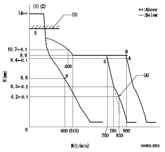
N:Pump speed
R:Rack position (mm)
(1)Target notch: K
(2)Tolerance for racks not indicated: +-0.05mm.
(3)RACK LIMIT
(4)Set idle sub-spring
----------
K=9
----------
----------
K=9
----------
Speed control lever angle
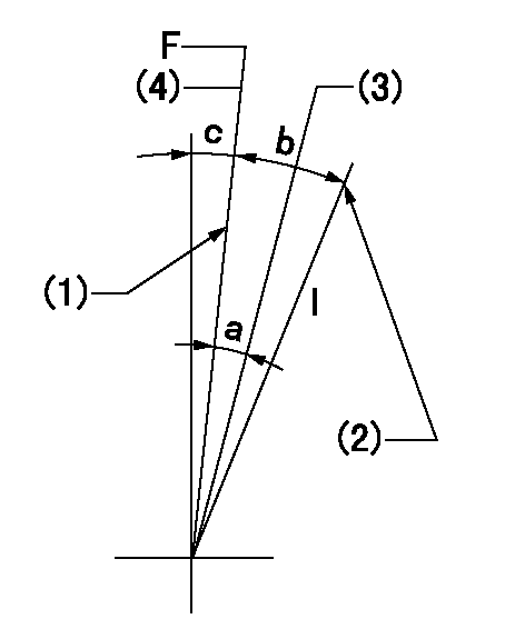
F:Full speed
I:Idle
(1)Stopper bolt setting
(2)Stopper bolt setting
(3)Set the pump speed at aa
(4)Set the pump speed at bb (at delivery)
----------
aa=750r/min bb=900r/min
----------
a=6deg+-5deg b=19deg+-5deg c=0deg+-5deg
----------
aa=750r/min bb=900r/min
----------
a=6deg+-5deg b=19deg+-5deg c=0deg+-5deg
Stop lever angle
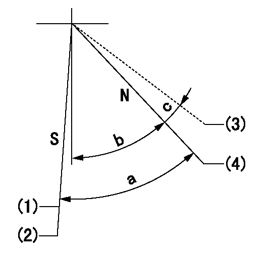
N:Pump normal
S:Stop the pump.
(1)Normal stop
(2)Rack position aa or less, pump speed bb
(3)Contacts normal side pin
(4)Clearance from the pin on the normal side: cc
----------
aa=6.3mm bb=0r/min cc=2.5+-0.5mm
----------
a=53deg+-5deg b=51deg+-5deg c=(6deg)
----------
aa=6.3mm bb=0r/min cc=2.5+-0.5mm
----------
a=53deg+-5deg b=51deg+-5deg c=(6deg)
Timing setting

(1)Pump vertical direction
(2)Coupling's key groove position at No 1 cylinder's beginning of injection
(3)-
(4)-
----------
----------
a=(50deg)
----------
----------
a=(50deg)
Information:
Do not operate or work on this product unless you have read and understood the instruction and warnings in the relevant Operation and Maintenance Manuals and relevant service literature. Failure to follow the instructions or heed the warnings could result in injury or death. Proper care is your responsibility.
There have been instances of the following diagnostic codes becoming active:
Table 1
J1939 Code CDL Code Code Description
1184-3 3782-3 Engine Turbocharger #1 Turbine Outlet Temperature : Voltage Above Normal
1184-4 3782-4 Engine Turbocharger #1 Turbine Outlet Temperature : Voltage Below Normal
3242-3 2452-3 DPF #1 Intake Temperature Sensor : Voltage Above Normal
3242-4 2452-4 DPF #1 Intake Temperature Sensor : Voltage Below Normal
4360-3 3105-3 Aftertreatment #1 SCR Catalyst Intake Gas Temperature Sensor : Voltage Above Normal
4360-4 3105-4 Aftertreatment #1 SCR Catalyst Intake Gas Temperature Sensor : Voltage Below Normal One root cause of the diagnostic codes has been identified as electrical noise overwriting data on the memory chip of the DPF/SCR intake temperature sensor. Improved sensor firmware has resolved this issue.A fault could not be found with some of the returned parts. A new troubleshooting procedure has been released. Refer to Troubleshooting, Sensor Signal (PWM) - Test.
Have questions with 101602-2921?
Group cross 101602-2921 ZEXEL
Hino
Hino
Hino
101602-2921
INJECTION-PUMP ASSEMBLY