Information injection-pump assembly
ZEXEL
101602-2910
1016022910
Rating:
Service parts 101602-2910 INJECTION-PUMP ASSEMBLY:
1.
_
5.
AUTOM. ADVANCE MECHANIS
6.
COUPLING PLATE
8.
_
9.
_
11.
Nozzle and Holder
23600-2142A
12.
Open Pre:MPa(Kqf/cm2)
19.6{200}
15.
NOZZLE SET
Cross reference number
ZEXEL
101602-2910
1016022910
Zexel num
Bosch num
Firm num
Name
101602-2910
INJECTION-PUMP ASSEMBLY
14BF PE6AD PE
14BF PE6AD PE
Calibration Data:
Adjustment conditions
Test oil
1404 Test oil ISO4113 or {SAEJ967d}
1404 Test oil ISO4113 or {SAEJ967d}
Test oil temperature
degC
40
40
45
Nozzle and nozzle holder
105780-8140
Bosch type code
EF8511/9A
Nozzle
105780-0000
Bosch type code
DN12SD12T
Nozzle holder
105780-2080
Bosch type code
EF8511/9
Opening pressure
MPa
17.2
Opening pressure
kgf/cm2
175
Injection pipe
Outer diameter - inner diameter - length (mm) mm 6-2-600
Outer diameter - inner diameter - length (mm) mm 6-2-600
Overflow valve
134424-0920
Overflow valve opening pressure
kPa
162
147
177
Overflow valve opening pressure
kgf/cm2
1.65
1.5
1.8
Tester oil delivery pressure
kPa
157
157
157
Tester oil delivery pressure
kgf/cm2
1.6
1.6
1.6
Direction of rotation (viewed from drive side)
Right R
Right R
Injection timing adjustment
Direction of rotation (viewed from drive side)
Right R
Right R
Injection order
1-4-2-6-
3-5
Pre-stroke
mm
3.45
3.42
3.48
Beginning of injection position
Drive side NO.1
Drive side NO.1
Difference between angles 1
Cal 1-4 deg. 60 59.75 60.25
Cal 1-4 deg. 60 59.75 60.25
Difference between angles 2
Cyl.1-2 deg. 120 119.75 120.25
Cyl.1-2 deg. 120 119.75 120.25
Difference between angles 3
Cal 1-6 deg. 180 179.75 180.25
Cal 1-6 deg. 180 179.75 180.25
Difference between angles 4
Cal 1-3 deg. 240 239.75 240.25
Cal 1-3 deg. 240 239.75 240.25
Difference between angles 5
Cal 1-5 deg. 300 299.75 300.25
Cal 1-5 deg. 300 299.75 300.25
Injection quantity adjustment
Adjusting point
A
Rack position
11
Pump speed
r/min
900
900
900
Average injection quantity
mm3/st.
69
67
71
Max. variation between cylinders
%
0
-3
3
Basic
*
Fixing the rack
*
Injection quantity adjustment_02
Adjusting point
C
Rack position
7.5+-0.5
Pump speed
r/min
450
450
450
Average injection quantity
mm3/st.
9
7.5
10.5
Max. variation between cylinders
%
0
-15
15
Fixing the rack
*
Injection quantity adjustment_03
Adjusting point
D
Rack position
-
Pump speed
r/min
100
100
100
Average injection quantity
mm3/st.
75
75
85
Fixing the lever
*
Rack limit
*
Test data Ex:
Governor adjustment
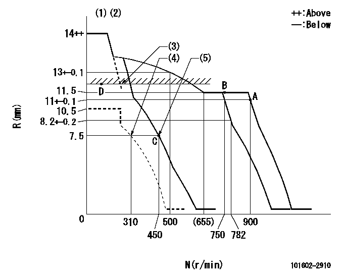
N:Pump speed
R:Rack position (mm)
(1)Target notch: K
(2)Tolerance for racks not indicated: +-0.05mm.
(3)RACK LIMIT
(4)Set idle sub-spring
(5)Main spring setting
----------
K=6
----------
----------
K=6
----------
Speed control lever angle
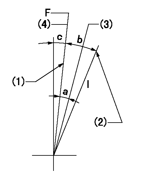
F:Full speed
I:Idle
(1)Stopper bolt setting
(2)Stopper bolt setting
(3)When pump speed set at aa
(4)Set the pump speed at bb.
----------
aa=750r/min bb=900r/min
----------
a=5deg+-5deg b=18deg+-5deg c=2deg+-5deg
----------
aa=750r/min bb=900r/min
----------
a=5deg+-5deg b=18deg+-5deg c=2deg+-5deg
Stop lever angle
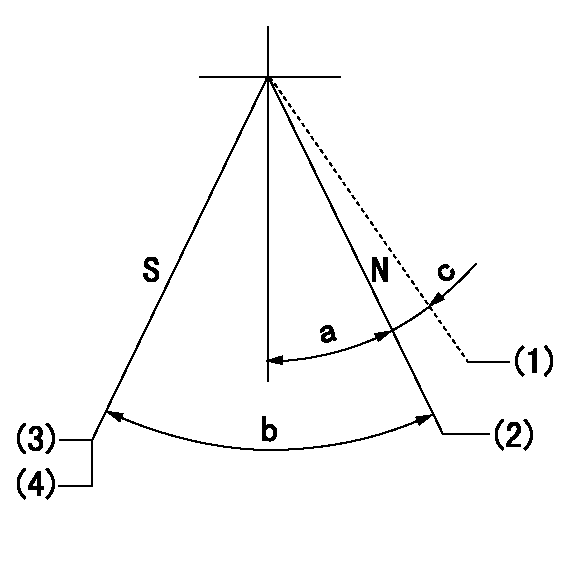
N:Pump normal
S:Stop the pump.
(1)Contacts normal side pin
(2)Distance from normal side pin = aa.
(3)Normal stop
(4)Rack position = bb or less, speed = cc
----------
aa=2.5+-0.5mm bb=7mm cc=0r/min
----------
a=27deg+-5deg b=53deg+-5deg c=(6deg)
----------
aa=2.5+-0.5mm bb=7mm cc=0r/min
----------
a=27deg+-5deg b=53deg+-5deg c=(6deg)
Timing setting

(1)Pump vertical direction
(2)Position of gear's standard threaded hole at No 1 cylinder's beginning of injection
(3)-
(4)-
----------
----------
a=(70deg)
----------
----------
a=(70deg)
Information:
Introduction
The problem that is identified below does not have a known permanent solution. Until a permanent solution is known, use the solution that is identified below.Problem
Fuel Injectors in 797F powered Off-Highway Trucks engines are not reaching expected mid-life target. The typical failure mode is a "-2" or a "-7" code on the fuel injectors.Solution
This will be an interim troubleshooting procedure to follow for trucks running with a special test software. Prior to executing this procedure, utilize Cat ® Electronic Technician (Cat ET) or Advisor to verify if any logged codes have been logged. Certain injector diagnostics do not notify the operator or light the check engine light upon activation."Fuel system verification-Test" procedure applies to trucks running with following software versions only.
Engine - LRC 3655600-31 (Test)
Engine - Tier II 5297866-05 (Test)
Engine - HAA (4x2) 3253178-39 (Test)
Engine - Tier II Custom 4727209-12 (Test)Troubleshooting Procedure
Table 1
Troubleshooting Test Steps Values Results
1. Check for Diagnostic Codes
A. Establish communication between Cat® (Electronic Technician) ET and the engine ECM. Cat ET must be configured for Dual Data Link Communications to perform this procedure. Refer to Troubleshooting, "Electronic Service Tools", if necessary.
B. Determine the diagnostic code that relates to an injector. Codes
Result: A -2 code is present.
Repair: Perform the following procedure:
1. Do not clear the diagnostic code.
Access the Fuel System Verification Test by accessing the following display screens:
- Diagnostics
- Diagnostic Tests
- Fuel System Verification Test
3. Perform the Fuel System Verification Test.
If the injector passes the test, the injector is "OK". Cat ET will clear the code.
Result: If the injector fails the test, perform the following procedure:
a. Replace the injector.
b. Flash program the trim file for the new injector into the ECM. Refer to Troubleshooting, "Injector Trim File - Install", if necessary.
c. Perform the Fuel System Verification Test again. This test will clear the active diagnostic code for the new injector. Verify that the original condition has been resolved.
Result: If the test
Have questions with 101602-2910?
Group cross 101602-2910 ZEXEL
Hino
Hino
101602-2910
INJECTION-PUMP ASSEMBLY