Information injection-pump assembly
BOSCH
9 400 610 580
9400610580
ZEXEL
101602-2870
1016022870
Rating:
Service parts 101602-2870 INJECTION-PUMP ASSEMBLY:
1.
_
5.
AUTOM. ADVANCE MECHANIS
6.
COUPLING PLATE
8.
_
9.
_
11.
Nozzle and Holder
23600-2142A
12.
Open Pre:MPa(Kqf/cm2)
19.6{200}
15.
NOZZLE SET
Cross reference number
BOSCH
9 400 610 580
9400610580
ZEXEL
101602-2870
1016022870
Zexel num
Bosch num
Firm num
Name
Calibration Data:
Adjustment conditions
Test oil
1404 Test oil ISO4113 or {SAEJ967d}
1404 Test oil ISO4113 or {SAEJ967d}
Test oil temperature
degC
40
40
45
Nozzle and nozzle holder
105780-8140
Bosch type code
EF8511/9A
Nozzle
105780-0000
Bosch type code
DN12SD12T
Nozzle holder
105780-2080
Bosch type code
EF8511/9
Opening pressure
MPa
17.2
Opening pressure
kgf/cm2
175
Injection pipe
Outer diameter - inner diameter - length (mm) mm 6-2-600
Outer diameter - inner diameter - length (mm) mm 6-2-600
Overflow valve
134424-0920
Overflow valve opening pressure
kPa
162
147
177
Overflow valve opening pressure
kgf/cm2
1.65
1.5
1.8
Tester oil delivery pressure
kPa
157
157
157
Tester oil delivery pressure
kgf/cm2
1.6
1.6
1.6
Direction of rotation (viewed from drive side)
Right R
Right R
Injection timing adjustment
Direction of rotation (viewed from drive side)
Right R
Right R
Injection order
1-4-2-6-
3-5
Pre-stroke
mm
3.45
3.42
3.48
Beginning of injection position
Drive side NO.1
Drive side NO.1
Difference between angles 1
Cal 1-4 deg. 60 59.75 60.25
Cal 1-4 deg. 60 59.75 60.25
Difference between angles 2
Cyl.1-2 deg. 120 119.75 120.25
Cyl.1-2 deg. 120 119.75 120.25
Difference between angles 3
Cal 1-6 deg. 180 179.75 180.25
Cal 1-6 deg. 180 179.75 180.25
Difference between angles 4
Cal 1-3 deg. 240 239.75 240.25
Cal 1-3 deg. 240 239.75 240.25
Difference between angles 5
Cal 1-5 deg. 300 299.75 300.25
Cal 1-5 deg. 300 299.75 300.25
Injection quantity adjustment
Adjusting point
A
Rack position
11
Pump speed
r/min
900
900
900
Average injection quantity
mm3/st.
69
67
71
Max. variation between cylinders
%
0
-3
3
Basic
*
Fixing the rack
*
Injection quantity adjustment_02
Adjusting point
C
Rack position
7.5+-0.5
Pump speed
r/min
450
450
450
Average injection quantity
mm3/st.
9
7.5
10.5
Max. variation between cylinders
%
0
-15
15
Fixing the rack
*
Injection quantity adjustment_03
Adjusting point
D
Rack position
-
Pump speed
r/min
100
100
100
Average injection quantity
mm3/st.
75
75
85
Fixing the lever
*
Rack limit
*
Test data Ex:
Governor adjustment
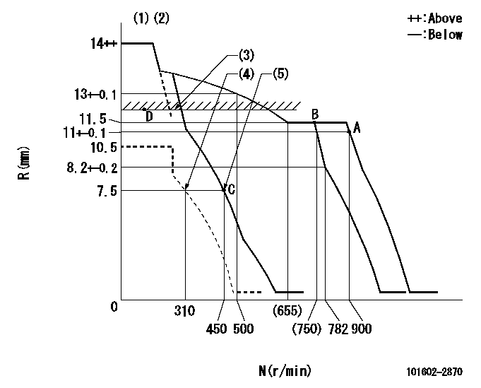
N:Pump speed
R:Rack position (mm)
(1)Target notch: K
(2)Tolerance for racks not indicated: +-0.05mm.
(3)RACK LIMIT
(4)Set idle sub-spring
(5)Main spring setting
----------
K=6
----------
----------
K=6
----------
Speed control lever angle
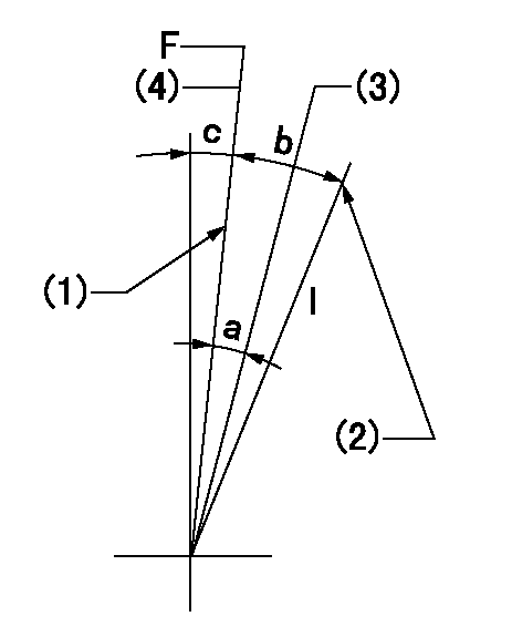
F:Full speed
I:Idle
(1)Stopper bolt setting
(2)Stopper bolt setting
(3)When pump speed set at aa
(4)Set the pump speed at bb.
----------
aa=750r/min bb=900r/min
----------
a=5deg+-5deg b=18deg+-5deg c=2deg+-5deg
----------
aa=750r/min bb=900r/min
----------
a=5deg+-5deg b=18deg+-5deg c=2deg+-5deg
Stop lever angle
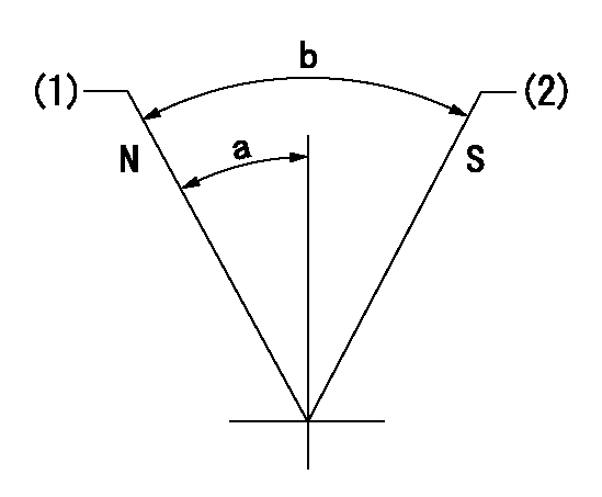
N:Pump normal
S:Stop the pump.
(1)Normal
(2)Rack position aa or less, pump speed bb
----------
aa=7mm bb=0r/min
----------
a=27deg+-5deg b=53deg+-5deg
----------
aa=7mm bb=0r/min
----------
a=27deg+-5deg b=53deg+-5deg
Timing setting

(1)Pump vertical direction
(2)Position of gear's standard threaded hole at No 1 cylinder's beginning of injection
(3)-
(4)-
----------
----------
a=(70deg)
----------
----------
a=(70deg)
Information:
Procedure
Illustration 1 g06220548
(1) TC Mark (Flywheel Housing)
(2) TC Mark (Flywheel)
Remove valve cover, and injector and rocker arm. Bring the piston of cylinder 4 to TDC.
Illustration 2 g06220554
(3) Dial Gauge
(4) Valve
(5) O-ring
Remove the #4 exhaust valve bridge arm and valve spring. Insert a small O-ring (5) so the valve does not fall into the cylinder.
Set dial gauge (3) on the tip of the valve (4).
Illustration 3 g06220569
(6) Tri - Square
(7) Flywheel Housing
(8) Flywheel
Illustration 4 g06220573
(7) Flywheel Housing
(8) Flywheel
(9) Reference Line
Turn the flywheel counterclockwise and measure the position where the tip of the valve is the highest.
Stop the flywheel at the position where the tip of the valve is the highest. Put a tri - square (6) on the flywheel housing (7) and the flywheel (8) and draw a reference line (9).Do not drop the valve (4) into the cylinder. When measuring the highest position of the tip of the valve, do not rotate the flywheel clockwise. If you go past the highest point of the valve, back up the flywheel slightly and measure the highest point of the valve. The reference line (9) indicates the TDC of the crankshaft.
Illustration 5 g06220579
Rotation Sensor Signal Interface Unit
Application: Use for reading rotation sensor signal.
(1) 9V Battery
(2) Switch
(3) 3-Terminal Regulator
(4) LED
(5) Clip (Red)
(6) Clip (Black)
(A) for Panasonic
(B) for Denso
(C) for Bosch cam angle
(D) for Bosch crank angle
((E)) Connector Side
(a) +9 V
(b) Signal
(c) GND
(d) +5 V
(e) Signal
(f) GND
Schematic to build Rotation Sensor Signal Interface.
Illustration 6 g06220581
(10) Rotation Sensor Signal Interface (Tool not available. Schematic to build tool available. Refer to Step 6.
(11) Tester
Illustration 7 g06220587
(12) Ground Terminal
(13) Output Terminal
(14) Crankshaft Position Sensor
Connect a connector of the rotation sensor signal interface unit (10) to the crankshaft position sensor (14). Connect each clip of the rotation sensor signal interface unit (10) to the same test lead color of the tester (11). Switch on the rotation sensor signal interface unit (10).
Illustration 8 g06220590
(15) Pulsar Gear
(16) 14th Tooth
(17) Missing Teeth
Turn the flywheel and make sure that the voltage of the crankshaft position sensor goes from 0→ 5 V or 5 → 0 V.
Rotate the flywheel and align the crankshaft position sensor to the part of the pulsar gear (15) that is missing teeth (17). The 14th tooth (16) from the missing teeth is standard.
Slowly turn flywheel counterclockwise and stop flywheel at the point where needle of the tester changes momentarily from 0 → 5 V, the 14th tooth.That point is where the crankshaft position sensor detects TDC.
Illustration 9 g06220608
(18) Crankshaft TDC
(19) Detection Point of Crankshaft Position Sensor TDC
Illustration 10 g06220612
(20) Interval
Set the tri - square (6) on the reference line (9) on the flywheel housing side and mark the detection point of crankshaft position sensor TDC (19) on the flywheel.
Measure the interval (20) between the crankshaft TDC (18) and the detection point of the crankshaft position sensor TDC (19).
Calculation of fuel injection timing correction 1.0 mm (0.039 in.): 0.321°.Corrected Angle = 0.321° X actual interval
Overwrite the injection timing correction value on the engine ecm registration website refer to REHS9707, "Registering Diesel Particulate Filter (DPF), Diesel Oxidation Catalyst (DOC),