Information injection-pump assembly
ZEXEL
101602-2860
1016022860
HINO
220204840A
220204840a

Rating:
Service parts 101602-2860 INJECTION-PUMP ASSEMBLY:
1.
_
5.
AUTOM. ADVANCE MECHANIS
7.
COUPLING PLATE
8.
_
9.
_
11.
Nozzle and Holder
23600-2133
12.
Open Pre:MPa(Kqf/cm2)
19.6{200}
15.
NOZZLE SET
Cross reference number
ZEXEL
101602-2860
1016022860
HINO
220204840A
220204840a
Zexel num
Bosch num
Firm num
Name
Calibration Data:
Adjustment conditions
Test oil
1404 Test oil ISO4113 or {SAEJ967d}
1404 Test oil ISO4113 or {SAEJ967d}
Test oil temperature
degC
40
40
45
Nozzle and nozzle holder
105780-8140
Bosch type code
EF8511/9A
Nozzle
105780-0000
Bosch type code
DN12SD12T
Nozzle holder
105780-2080
Bosch type code
EF8511/9
Opening pressure
MPa
17.2
Opening pressure
kgf/cm2
175
Injection pipe
Outer diameter - inner diameter - length (mm) mm 6-2-600
Outer diameter - inner diameter - length (mm) mm 6-2-600
Overflow valve
134424-0920
Overflow valve opening pressure
kPa
162
147
177
Overflow valve opening pressure
kgf/cm2
1.65
1.5
1.8
Tester oil delivery pressure
kPa
157
157
157
Tester oil delivery pressure
kgf/cm2
1.6
1.6
1.6
Direction of rotation (viewed from drive side)
Right R
Right R
Injection timing adjustment
Direction of rotation (viewed from drive side)
Right R
Right R
Injection order
1-4-2-6-
3-5
Pre-stroke
mm
4.8
4.77
4.83
Beginning of injection position
Drive side NO.1
Drive side NO.1
Difference between angles 1
Cal 1-4 deg. 60 59.75 60.25
Cal 1-4 deg. 60 59.75 60.25
Difference between angles 2
Cyl.1-2 deg. 120 119.75 120.25
Cyl.1-2 deg. 120 119.75 120.25
Difference between angles 3
Cal 1-6 deg. 180 179.75 180.25
Cal 1-6 deg. 180 179.75 180.25
Difference between angles 4
Cal 1-3 deg. 240 239.75 240.25
Cal 1-3 deg. 240 239.75 240.25
Difference between angles 5
Cal 1-5 deg. 300 299.75 300.25
Cal 1-5 deg. 300 299.75 300.25
Injection quantity adjustment
Adjusting point
A
Rack position
10
Pump speed
r/min
900
900
900
Average injection quantity
mm3/st.
117
115.5
118.5
Max. variation between cylinders
%
0
-3.5
3.5
Basic
*
Fixing the rack
*
Boost pressure
kPa
124
124
Boost pressure
mmHg
930
930
Injection quantity adjustment_02
Adjusting point
-
Rack position
6.9+-0.5
Pump speed
r/min
400
400
400
Average injection quantity
mm3/st.
10
9
11
Max. variation between cylinders
%
0
-10
10
Fixing the rack
*
Boost pressure
kPa
0
0
0
Boost pressure
mmHg
0
0
0
Remarks
Adjust only variation between cylinders; adjust governor according to governor specifications.
Adjust only variation between cylinders; adjust governor according to governor specifications.
Boost compensator adjustment
Pump speed
r/min
500
500
500
Rack position
R1-2.1
Boost pressure
kPa
52
49.3
54.7
Boost pressure
mmHg
390
370
410
Boost compensator adjustment_02
Pump speed
r/min
500
500
500
Rack position
R1(11.5)
Boost pressure
kPa
111
104.3
117.7
Boost pressure
mmHg
830
780
880
Test data Ex:
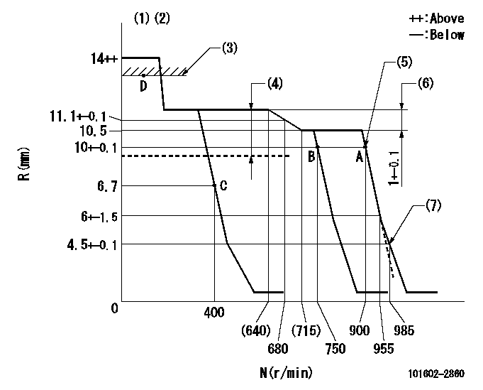
Governor adjustment

N:Pump speed
R:Rack position (mm)
(1)Notch fixed: K
(2)Tolerance for racks not indicated: +-0.05mm.
(3)Excessive fuel lever setting (boost pressure 0)
(4)Boost compensator stroke: BCL
(5)Main spring setting
(6)Rack difference between N = N1 and N = N2
(7)Set idle sub-spring
----------
K=10 BCL=2.1+-0.1mm N1=850r/min N2=500r/min
----------
----------
K=10 BCL=2.1+-0.1mm N1=850r/min N2=500r/min
----------
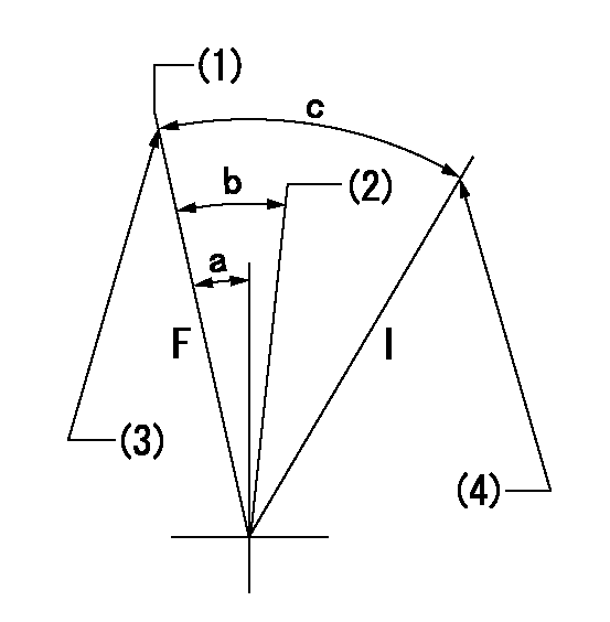
Speed control lever angle

F:Full speed
I:Idle
(1)Set the pump speed at aa. ( At delivery )
(2)When pump speed set at bb
(3)Stopper bolt setting
(4)Stopper bolt setting
----------
aa=900r/min bb=750r/min
----------
a=3deg+-5deg b=5.5deg+-5deg c=20deg+-5deg
----------
aa=900r/min bb=750r/min
----------
a=3deg+-5deg b=5.5deg+-5deg c=20deg+-5deg
Stop lever angle

N:Pump normal
S:Stop the pump.
(1)Rack position aa or less, pump speed bb
----------
aa=6.2mm bb=0r/min
----------
a=27deg+-5deg b=53deg+-5deg
----------
aa=6.2mm bb=0r/min
----------
a=27deg+-5deg b=53deg+-5deg
0000001101

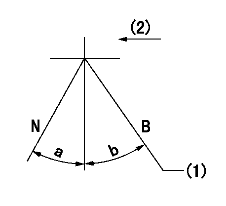
N:Normal
B:When boosted
(1)Rack position = aa (point D) at boost pressure 0.
(2)Drive side
----------
aa=13.2+-0.1mm
----------
a=(15deg) b=(13deg)
----------
aa=13.2+-0.1mm
----------
a=(15deg) b=(13deg)
Timing setting

(1)Pump vertical direction
(2)Coupling's key groove position at No 1 cylinder's beginning of injection
(3)-
(4)-
----------
----------
a=(50deg)
----------
----------
a=(50deg)
Information:
Every attempt is made to provide accurate, up-to-date information. By the use of this document, you agree that Caterpillar Inc. is not responsible for errors or omissions.
The information that is provided is the latest recommendations for Cat diesel engines that are covered by this Special Publication. This information supersedes all previous recommendations which have been published for Cat diesel engines that are covered by this Special Publication. Special fluids are required for some engines. These fluids will still be necessary in those engines. Refer to the applicable Operation and Maintenance Manual.This publication is a supplement to the Operation and Maintenance Manual. This publication does not replace the engine-specific Operation and Maintenance Manuals.
These recommendations are subject to change without notice. Consult your local Cat dealer for the most up to date recommendations.
Failure to follow the recommendations found in this Special Publication can cause engine failures, shortened engine service life, and reduced engine performance.In order to avoid potential damage to your Cat Cat engine, only purchase Cat fluids and Cat filters through your Cat dealer or Cat authorized outlets. For a list of authorized Cat parts outlets in your area, consult your Cat dealer.If you purchase what appear to be Cat fluids and/or Cat filters through other outlets/sources, you are at a very high risk of purchasing counterfeit (“look-alike”) products.Counterfeit or “look-alike” products may visually appear the same as the original Cat product. The product performance and internal quality will typically be very low.Counterfeit or “look-alike” products have a very high likelihood of causing and/or allowing engine and/or machine compartment damage.Many of the guidelines, recommendations, and requirements that are provided in this Special Publication are interrelated. Before using the provided information, The user is responsible to read this Special Publication and understand the information provided.The user is responsible to follow all safety guidelines found in this Special Publication and in the engine Operation and Maintenance Manual when performing all recommended and/or required engine, engine systems, and/or machine maintenance.For questions concerning the information presented in this Special Publication and/or in your product Operation and Maintenance Manual, and/or for additional guidelines and recommendations (including maintenance interval recommendations/requirements) consult your Cat dealer.Commercial products that make generic claims of meeting “Cat” and/or “Cat” requirements without listing the specific Cat recommendations and/or requirements that are met may not provide acceptable performance. Reduced engine and/or machine fluid compartment life may result. Refer to this Special Publication and refer to the product Operation and Maintenance Manual for Cat fluids recommendations and/or requirements.Use of fluids that do not meet at least the minimum performance recommendations and/or requirements may lead to lower compartment performance and/or compartment failure.Problems/failures that are caused by using fluids that do not meet the minimum recommended and/or required performance level for the compartment are not warrantable by Caterpillar Inc.. The fluid manufacturer and customer are responsible.When fluids made by other manufacturers are used on Cat products, the Cat warranty is not affected simply because of such use. Failures that result from the installation or usage
