Information injection-pump assembly
BOSCH
9 400 614 800
9400614800
ZEXEL
101602-2852
1016022852
HINO
220204820B
220204820b

Rating:
Service parts 101602-2852 INJECTION-PUMP ASSEMBLY:
1.
_
5.
AUTOM. ADVANCE MECHANIS
7.
COUPLING PLATE
8.
_
9.
_
11.
Nozzle and Holder
236002900A
12.
Open Pre:MPa(Kqf/cm2)
17.7{180}/21.6{220}
14.
NOZZLE
Cross reference number
BOSCH
9 400 614 800
9400614800
ZEXEL
101602-2852
1016022852
HINO
220204820B
220204820b
Zexel num
Bosch num
Firm num
Name
101602-2852
9 400 614 800
220204820B HINO
INJECTION-PUMP ASSEMBLY
H07D-C K
H07D-C K
Calibration Data:
Adjustment conditions
Test oil
1404 Test oil ISO4113 or {SAEJ967d}
1404 Test oil ISO4113 or {SAEJ967d}
Test oil temperature
degC
40
40
45
Nozzle and nozzle holder
105780-8140
Bosch type code
EF8511/9A
Nozzle
105780-0000
Bosch type code
DN12SD12T
Nozzle holder
105780-2080
Bosch type code
EF8511/9
Opening pressure
MPa
17.2
Opening pressure
kgf/cm2
175
Injection pipe
Outer diameter - inner diameter - length (mm) mm 6-2-600
Outer diameter - inner diameter - length (mm) mm 6-2-600
Overflow valve
134424-0920
Overflow valve opening pressure
kPa
162
147
177
Overflow valve opening pressure
kgf/cm2
1.65
1.5
1.8
Tester oil delivery pressure
kPa
157
157
157
Tester oil delivery pressure
kgf/cm2
1.6
1.6
1.6
Direction of rotation (viewed from drive side)
Right R
Right R
Injection timing adjustment
Direction of rotation (viewed from drive side)
Right R
Right R
Injection order
1-4-2-6-
3-5
Pre-stroke
mm
4.8
4.77
4.83
Beginning of injection position
Drive side NO.1
Drive side NO.1
Difference between angles 1
Cal 1-4 deg. 60 59.75 60.25
Cal 1-4 deg. 60 59.75 60.25
Difference between angles 2
Cyl.1-2 deg. 120 119.75 120.25
Cyl.1-2 deg. 120 119.75 120.25
Difference between angles 3
Cal 1-6 deg. 180 179.75 180.25
Cal 1-6 deg. 180 179.75 180.25
Difference between angles 4
Cal 1-3 deg. 240 239.75 240.25
Cal 1-3 deg. 240 239.75 240.25
Difference between angles 5
Cal 1-5 deg. 300 299.75 300.25
Cal 1-5 deg. 300 299.75 300.25
Injection quantity adjustment
Adjusting point
A
Rack position
9.1
Pump speed
r/min
900
900
900
Average injection quantity
mm3/st.
82.5
81.5
83.5
Max. variation between cylinders
%
0
-3.5
3.5
Basic
*
Fixing the rack
*
Injection quantity adjustment_02
Adjusting point
-
Rack position
7.3+-0.5
Pump speed
r/min
490
490
490
Average injection quantity
mm3/st.
10
9
11
Max. variation between cylinders
%
0
-10
10
Fixing the rack
*
Remarks
Adjust only variation between cylinders; adjust governor according to governor specifications.
Adjust only variation between cylinders; adjust governor according to governor specifications.
Injection quantity adjustment_03
Adjusting point
D
Rack position
9.9++
Pump speed
r/min
100
100
100
Average injection quantity
mm3/st.
125
125
135
Fixing the lever
*
Rack limit
*
Test data Ex:
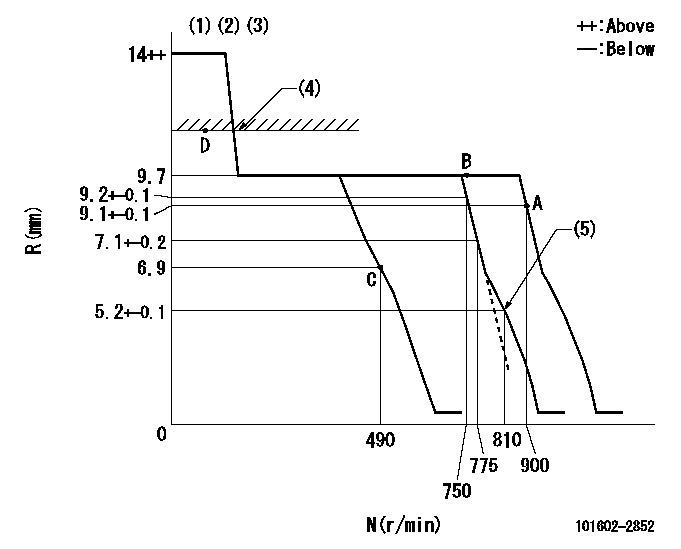
Governor adjustment

N:Pump speed
R:Rack position (mm)
(1)Target notch: K
(2)Tolerance for racks not indicated: +-0.05mm.
(3)The torque control spring does not operate.
(4)RACK LIMIT
(5)Set idle sub-spring
----------
K=8
----------
----------
K=8
----------
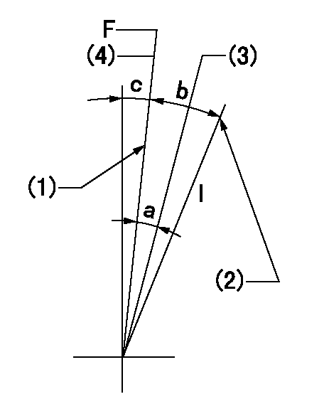
Speed control lever angle

F:Full speed
I:Idle
(1)Stopper bolt setting
(2)Stopper bolt setting
(3)When pump speed set at aa
(4)Set the pump speed at bb.
----------
aa=750r/min bb=900r/min
----------
a=5deg+-5deg b=16deg+-5deg c=1deg+-5deg
----------
aa=750r/min bb=900r/min
----------
a=5deg+-5deg b=16deg+-5deg c=1deg+-5deg
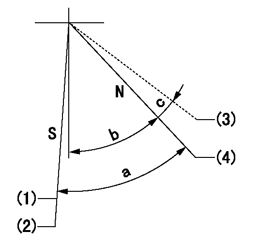
Stop lever angle

N:Pump normal
S:Stop the pump.
(1)Normal stop
(2)Rack position aa or less, pump speed bb
(3)Contacts normal side pin
(4)Clearance from the pin on the normal side: cc
----------
aa=6.4mm bb=0r/min cc=2.5+-0.5mm
----------
a=53deg+-5deg b=51deg+-5deg c=(6deg)
----------
aa=6.4mm bb=0r/min cc=2.5+-0.5mm
----------
a=53deg+-5deg b=51deg+-5deg c=(6deg)
Timing setting

(1)Pump vertical direction
(2)Coupling's key groove position at No 1 cylinder's beginning of injection
(3)-
(4)-
----------
----------
a=(50deg)
----------
----------
a=(50deg)
Information:
Heavy fuel oil, residual fuel, or blended fuel can be used only in Cat 3600 Series engines that are configured to use heavy fuel oil.DO NOT use these types of fuel in diesel engines that are configured to use distillate diesel fuel. Do not use these types of fuel in engines that are Tier 4 EPA certified. Failure to follow this recommendation will result in severe wear of components and engine failure.
Gas Oil - A light distillate fuel which does not contain residual fuel. Gas oil is approximately ASTM No.1 diesel fuel.Marine Diesel - A distillate fuel that boils at a higher temperature than gas oil. This fuel varies from ASTM No.2 to ASTM No.4. The composition can vary within the following range: ASTM No.2 diesel fuel, No.2 that is contaminated with heavier fuel in the bottom of a tanker and No.2 that is blended with as much as 20 percent of residual fuel.
Do NOT use fuel that is blended with residual fuel in diesel engines that are configured to use distillate fuel. Severe component wear and component failures will result if this type of fuel is used in diesel engines that are configured to use distillate fuel.
Table 1 lists some permissible marine diesel fuels.Blended Fuel Oil - A blend of distillate and residual fuel. This fuel is blended to the viscosity that is requested by the operator or the manufacturer of the engine. Blended fuel is also referred to as heavy fuel oil (HFO).Note: Do NOT use blended fuel in Cat diesel engines that are configured to use distillate fuel. Severe component wear and component failures will result if this type of fuel is used in diesel engines that are configured to use distillate fuel.Residual Fuel - A residue from the distillation of crude oil in a refinery. Residual fuel is also referred to as heavy fuel oil (HFO).Note: DO NOT use residual fuel in Cat diesel engines that are configured to use distillate fuel. Severe component wear and component failures will result if this type of fuel is used in diesel engines that are configured to use distillate fuel.DO NOT use fuels that are classified as CIMAC DC or ISO 8217F-DMC.The use of fuels that are classified as CIMAC DC or ISO 8217F-DMC can reduce the service life of components.Only use fuels that meet or exceed Cat recommendations. The use of fuels that are not recommended can reduce the service life of components.The classifications that are listed in Table 1 are established by the International Standards Organization (ISO). Fuels which meet the classifications that are listed in Table 1 are permissible for use in Cat 3600 Series diesel engines that are configured to use distillate fuel. Fuels classified by the Council International Des Machines a Combustion (CIMAC) that are equivalent to the ISO Classifications indicted in Table 1 are also permissible for use in Cat 3600 and C280 Series engines.
Table 1
Marine Distillate Diesel Fuels That Are Permissible for Use In Caterpillar 3600 Series and C280 Series
Have questions with 101602-2852?
Group cross 101602-2852 ZEXEL
Hino
Hino
Hino
Hino
Hino
Hino
101602-2852
9 400 614 800
220204820B
INJECTION-PUMP ASSEMBLY
H07D-C
H07D-C